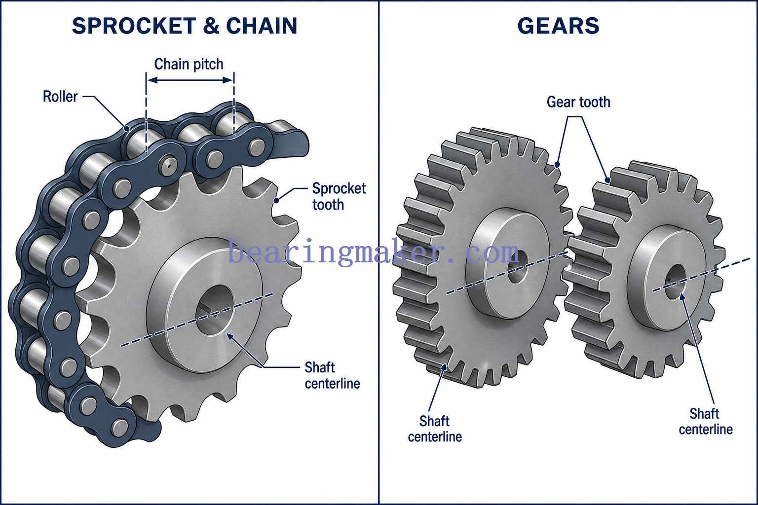
A sprocket is a toothed mechanical wheel designed to engage with a chain, track, or other positively driven element. In a typical roller-chain drive, the sprocket teeth engage the chain rollers and transfer rotational power from one shaft to another.
Unlike a friction belt drive, a properly designed sprocket-and-chain system provides positive engagement, which means the drive ratio is determined mechanically rather than by friction. Unlike gears, sprockets do not mesh directly with another toothed wheel, allowing them to transmit power between shafts separated by a relatively large distance.
Common sprockets can be classified by:
- Hub configuration: plate, single-hub, double-hub, and special hub designs
- Number of chain strands: simplex, duplex, triplex, and multi-strand
- Mounting method: pilot bore, finished bore, taper-bushed, keyed, or custom bore
- Function: drive, driven, idler, conveyor, segmental, or specialty sprockets
- Chain standard: inch-series roller chain, metric roller chain, engineering chain, conveyor chain, and other specialized chains
Sprockets are widely used in bicycles, motorcycles, conveyors, packaging machinery, agricultural equipment, construction equipment, automated production lines, and many other mechanical systems.
Sprocket vs. Gear: What Is the Difference?
Although sprockets and gears both have teeth, they work in fundamentally different ways.
| Feature | Sprocket | Gear |
|---|---|---|
| Engages with | Chain, track, or similar element | Another gear |
| Power transfer | Through chain engagement | Direct tooth-to-tooth contact |
| Shaft spacing | Can accommodate relatively large shaft distances | Usually requires closely positioned shafts |
| Slip | Positive engagement under normal operation | Positive engagement |
| Alignment requirements | Important, but flexible shaft spacing is possible | Precise center distance and alignment required |
| Speed ratio | Determined by sprocket tooth counts | Determined by gear tooth counts |
| Noise | Moderate; affected by chain speed and polygonal action | Can be very low with precision gearing |
| Lubrication | Chain and tooth engagement usually require lubrication | Gear teeth generally require lubrication |
| Typical applications | Conveyors, motorcycles, bicycles, machinery | Gearboxes, transmissions, machine tools |
| Long-distance transmission | Well suited | Generally not practical |
| Direction change | Normally requires chain routing or additional sprockets | Easily achieved using gear arrangements |
A sprocket therefore should not simply be described as a “gear for a chain.” Its tooth profile, operating geometry, wear mechanisms, and design considerations are different from those of conventional gears.
How Does a Sprocket Work?
A sprocket transfers power through the sequential engagement of its teeth with a chain.
Consider a simple two-sprocket drive:
- A motor rotates the driving sprocket.
- The driving sprocket teeth engage the chain rollers.
- The rotating sprocket pulls the chain along its pitch line.
- The moving chain engages the driven sprocket.
- The driven sprocket rotates the second shaft.
Because the chain physically engages the sprocket teeth, the relationship between the two sprockets remains synchronized as long as the chain remains properly engaged.
Chain Pitch Is Critical
One of the most important dimensions is chain pitch.
Chain pitch is the center-to-center distance between adjacent chain pins.
The sprocket tooth spacing must correspond to that pitch.
For example:
- A 1/2-inch-pitch roller chain requires a sprocket designed for that chain pitch.
- A metric chain with a 12.7 mm pitch requires a compatible metric-chain sprocket geometry.
Pitch alone, however, is not always enough to establish compatibility. Roller diameter, inner width, strand configuration, and chain standard must also be checked.
A sprocket designed for one chain series should therefore not automatically be considered interchangeable with another chain simply because the nominal pitch appears similar.
What Is the Polygon Effect?
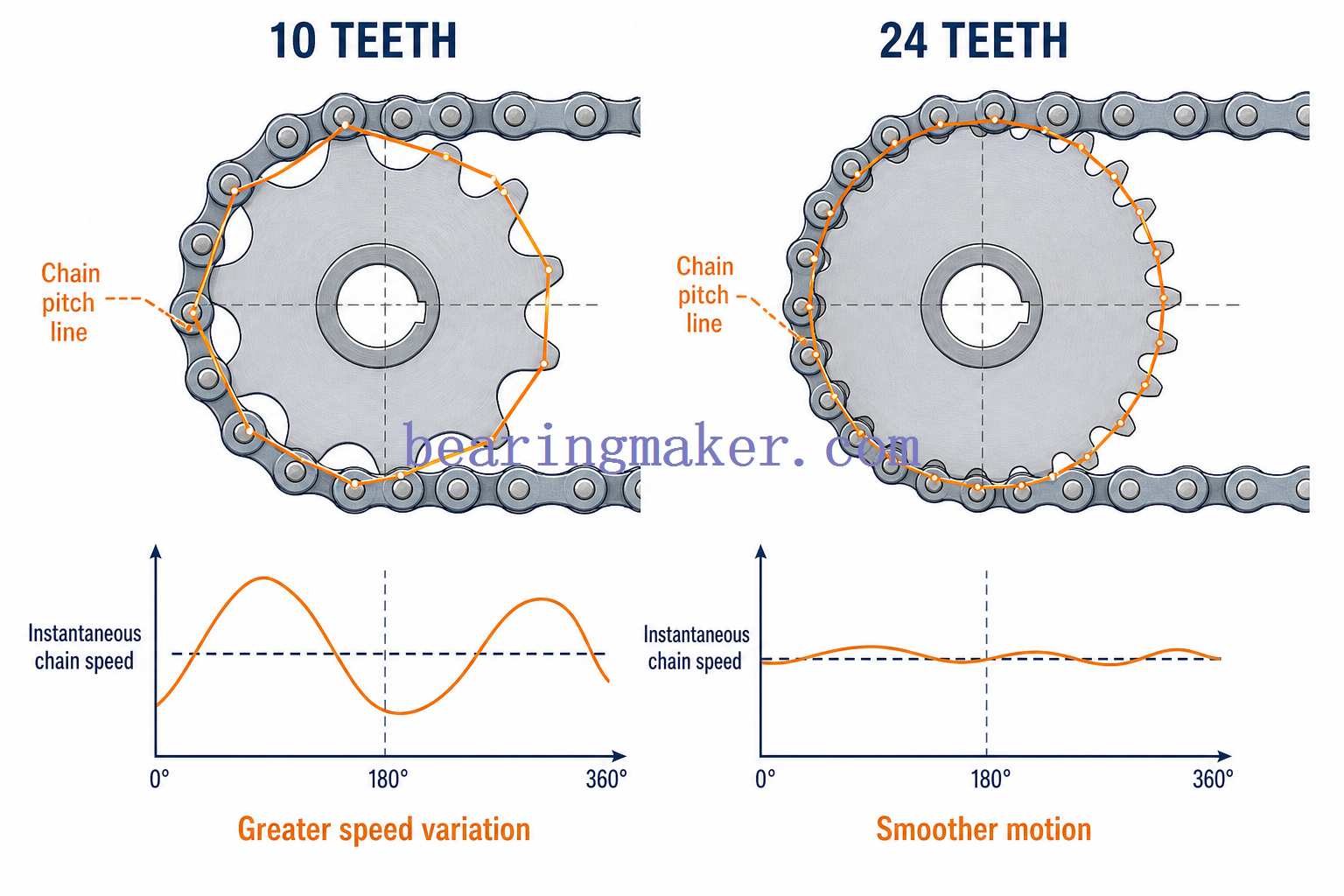
Unlike a belt running around a perfectly circular pulley, a roller chain consists of individual rigid pitches.
As the chain engages a sprocket, its pitch line forms a polygon around the sprocket rather than a perfect circle.
This produces a small periodic change in instantaneous chain speed known as the:
polygon effect, or chordal action.
The effect becomes more noticeable when the small sprocket has very few teeth.
Possible consequences include:
- vibration
- speed fluctuation
- increased noise
- dynamic chain loading
- accelerated wear
- poorer motion uniformity
Using a larger number of teeth on the small sprocket generally reduces chordal action.
For many conventional roller-chain drives, designers prefer approximately 17 teeth or more on the smaller sprocket where space and speed ratio permit. Very high-speed or precision applications may benefit from even larger tooth counts.
This is a design guideline rather than a universal requirement; allowable tooth count depends on chain type, speed, load, space, and duty cycle.
Understanding the Main Parts of a Sprocket
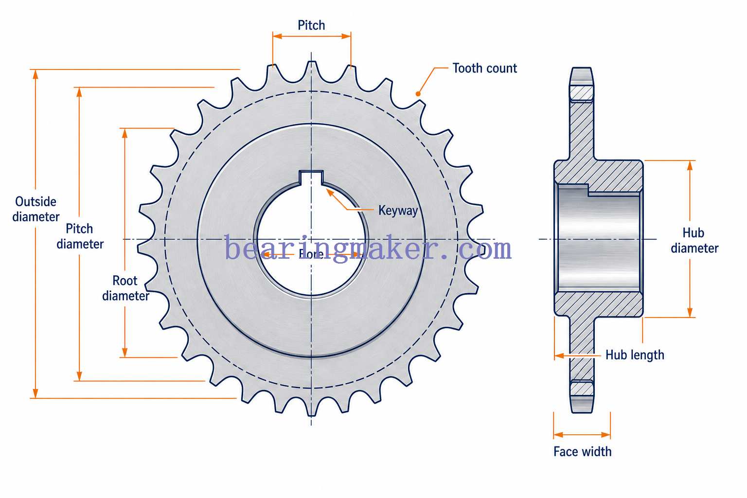
Before selecting a sprocket, it helps to understand its important dimensions and terminology.
1. Teeth
The teeth are the projections around the sprocket circumference that engage the chain rollers.
Their geometry is designed around the dimensions and articulation of the intended chain.
2. Number of Teeth
The number of teeth is usually represented by:
N or Z
Tooth count affects:
- speed ratio
- torque ratio
- sprocket diameter
- chain wrap
- chordal action
- wear rate
- overall drive size
3. Pitch
Pitch, usually represented by P, is the distance between adjacent chain pins.
It is one of the fundamental dimensions used to define a roller-chain system.
4. Pitch Circle and Pitch Diameter
The pitch circle is an imaginary circle passing through the centers of the chain rollers when the chain is properly engaged.
Its diameter is called the:
Pitch Diameter (PD)
Pitch diameter is more useful for drive calculations than outside diameter because it represents the effective operating geometry of the chain.
5. Outside Diameter
The Outside Diameter (OD) is measured across the outermost tips of the sprocket teeth.
It is important when checking:
- machine-envelope clearance
- guards
- housings
- neighboring components
- maximum allowable sprocket size
Outside diameter should not normally be used as the primary diameter for calculating drive ratio.
6. Root or Bottom Diameter
The root diameter is measured across the bottoms of opposing tooth spaces.
It is related to roller seating and tooth-root geometry.
Exact values depend on the applicable sprocket tooth profile and chain dimensions.
7. Bore
The bore is the central hole through which the sprocket mounts to a shaft.
Common bore configurations include:
- pilot bore
- plain finished bore
- keyed bore
- splined bore
- taper-bushing bore
- custom machined bore
8. Hub
The hub is the thicker portion surrounding the bore.
It provides additional:
- shaft engagement length
- structural strength
- keyway support
- set-screw space
- torque-transmission capability
9. Keyway
A keyway allows a mechanical key to transmit torque between the shaft and sprocket.
The shaft keyway and sprocket keyway must be compatible with the selected key.
10. Face Width
Face width is the axial width of the tooth section.
It must correspond to the chain width and strand configuration.
Basic Sprocket Calculations
Several simple formulas are useful when designing a chain drive.
Pitch Diameter
For a roller-chain sprocket:
[
PD = \frac{P}{\sin(180^\circ/N)}
]
Where:
- PD = pitch diameter
- P = chain pitch
- N = number of sprocket teeth
Example
For a sprocket with:
- chain pitch = 0.500 in
- number of teeth = 20
[
PD = \frac{0.500}{\sin(180^\circ/20)}
]
[
PD \approx 3.196\text{ in}
]
So the sprocket has a pitch diameter of approximately 3.20 inches.
How Sprocket Ratio Affects Speed and Torque
One of the most useful sprocket calculations is the drive ratio.
If:
- (N_1) = number of teeth on the driving sprocket
- (N_2) = number of teeth on the driven sprocket
then:
[
Drive\ Ratio = \frac{N_2}{N_1}
]
and approximately:
[
RPM_2 = RPM_1 \times \frac{N_1}{N_2}
]
Example
Suppose:
- driving sprocket = 15 teeth
- driven sprocket = 45 teeth
- motor speed = 900 rpm
Then:
[
Drive\ Ratio = \frac{45}{15}=3
]
The output speed is approximately:
[
900 \times \frac{15}{45}=300\ rpm
]
Ignoring system losses:
- output speed is reduced to about one-third
- output torque is increased correspondingly
Actual delivered torque will be slightly lower than the theoretical value because of friction and other mechanical losses.
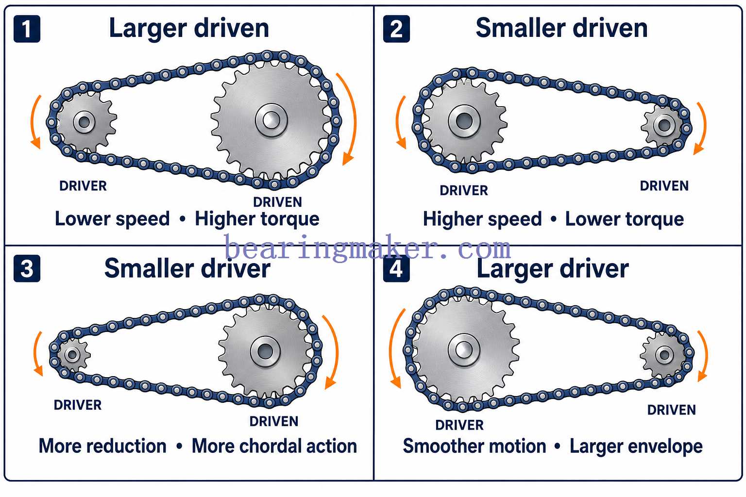
What Happens When You Change Tooth Count?
For a fixed driving sprocket:
Larger driven sprocket:
- lower output speed
- higher theoretical output torque
- larger overall package
Smaller driven sprocket:
- higher output speed
- lower theoretical output torque
For a fixed driven sprocket:
Smaller driving sprocket:
- greater reduction ratio
- potentially greater chordal action
- often greater articulation and wear
Larger driving sprocket:
- smoother chain motion
- lower chain articulation
- larger drive envelope
Types of Sprockets
Sprockets can be classified in several different ways.
Sprocket Types Quick Reference
| Classification | Common Types | Main Purpose |
|---|---|---|
| Hub configuration | Plate, single hub, double hub | Defines mounting geometry and support |
| Strand count | Simplex, duplex, triplex | Determines compatibility with multi-strand chain |
| Bore configuration | Pilot, finished, keyed, taper-bushed | Determines shaft attachment method |
| Function | Drive, driven, idler | Determines role within chain system |
| Construction | Solid, welded, segmental | Affects strength and maintenance |
| Application | Power transmission, conveyor, miniature, heavy engineering | Optimizes sprocket for operating environment |
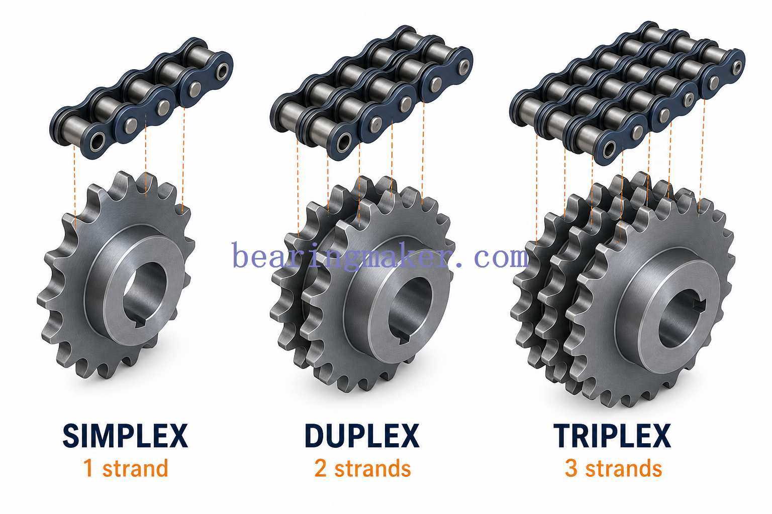
Sprockets by Strand Configuration
Simplex Sprockets
A simplex sprocket has one row of teeth and operates with a single-strand chain.
It is the most common arrangement for:
- general machinery
- small conveyors
- agricultural equipment
- packaging systems
- motorcycles
- light and medium industrial drives
Advantages include:
- compact width
- lower cost
- simple alignment
- wide component availability
Duplex Sprockets
A duplex sprocket has two parallel rows of teeth and operates with a double-strand chain.
It is used when greater power capacity is required without greatly increasing chain pitch.
Common applications include:
- industrial machinery
- processing equipment
- heavy conveyors
- higher-torque drives
Triplex Sprockets
Triplex sprockets have three parallel tooth rows for triple-strand chains.
They are used in more heavily loaded systems where a single chain strand would not provide sufficient capacity.
An important point is that multi-strand capacity does not increase perfectly linearly with strand count.
Manufacturing tolerances, chain loading, alignment, and load sharing mean that two strands should not simply be assumed to provide exactly twice the capacity of one strand.
Actual power ratings should therefore be determined using the relevant chain-rating tables and multi-strand factors.
Sprockets by Hub Design
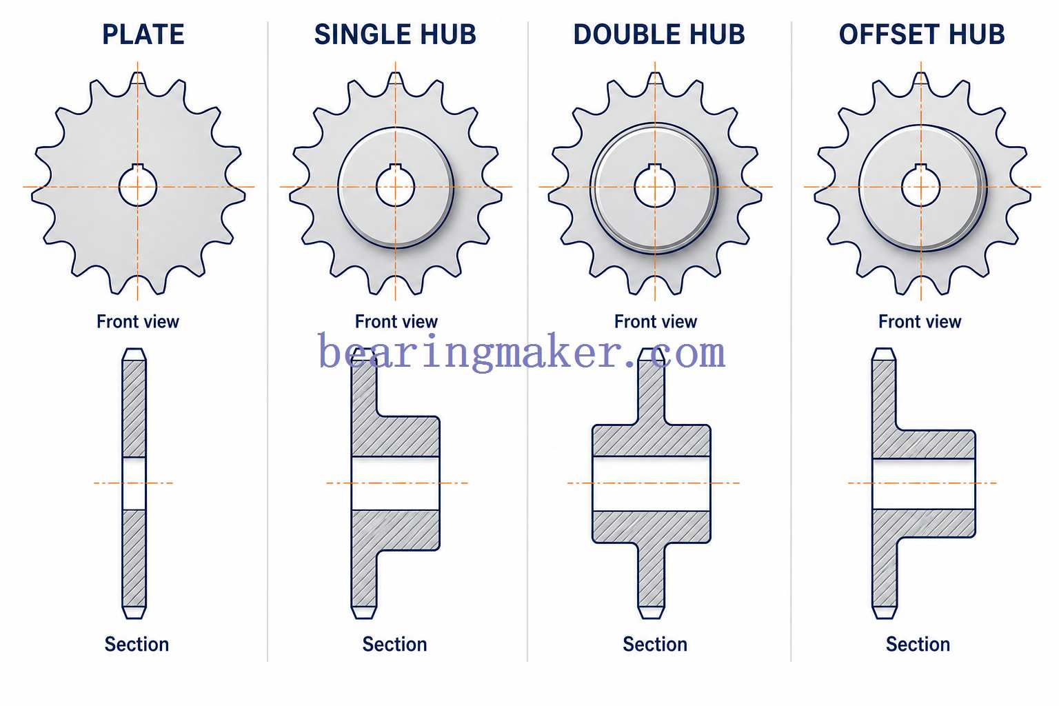
Hub terminology varies by market and manufacturer, but several general forms are widely recognized.
Type A — Plate Sprocket
A plate sprocket has no projecting hub.
Advantages:
- very compact
- low weight
- easy to incorporate into welded assemblies
Common uses:
- confined spaces
- conveyor assemblies
- custom machine fabrication
- sprockets mounted to another hub or structure
Type B — Single-Hub Sprocket
A single-hub sprocket has a hub projecting from one side.
This provides more material around the bore and makes it suitable for:
- keyways
- set screws
- conventional shaft mounting
It is one of the most widely used industrial configurations.
Type C — Double-Hub Sprocket
A double-hub sprocket has hub extensions on both sides of the tooth plate.
Advantages can include:
- greater hub length
- increased shaft support
- more symmetrical geometry
- additional material around the bore
It is useful where shaft attachment or structural requirements justify the additional width.
Special and Offset Hub Designs
Custom sprockets may use:
- asymmetric hubs
- extended hubs
- recessed hubs
- welded hubs
- flanged hubs
- integrated shaft features
These configurations are generally chosen because of machine-layout or mounting constraints rather than chain engagement itself.
Sprockets by Mounting Method
Pilot Bore Sprockets
A pilot bore is intentionally supplied smaller than the final required shaft diameter.
The user or machine shop can then finish-machine:
- final bore diameter
- keyway
- set-screw holes
- other mounting features
Pilot-bore sprockets are useful for custom equipment and non-standard shaft sizes.
Finished Bore Sprockets
Finished bore sprockets are supplied with a completed bore and, where required, a keyway and set screw.
They are convenient when:
- shaft dimensions are standardized
- installation speed matters
- no additional machining is desired
Taper-Bushed Sprockets
These sprockets use a separate tapered bushing between the sprocket and shaft.
When tightened, the tapered interface generates clamping force.
Advantages can include:
- relatively easy installation
- convenient removal
- good shaft grip
- multiple shaft sizes using interchangeable bushings
- reduced need to manufacture a completely different sprocket for every bore size
They are common in industrial drives where components may need periodic replacement.
Splined and Special-Bore Sprockets
Some high-torque or specialized applications use:
- splines
- polygonal shaft interfaces
- locking assemblies
- shrink fits
- custom profiles
These designs can provide greater torque-transfer capability or improved concentricity compared with a basic plain bore.
Specialized Sprocket Types
Idler Sprockets
An idler sprocket usually does not transmit motor torque to an output shaft.
Instead, it may:
- guide the chain
- increase chain wrap
- control the chain path
- support a long chain span
- assist with tension management
Some idler sprockets contain a bearing so that they can rotate freely around a stationary shaft or stud.
Hunting-Tooth Arrangements
In certain chain-drive combinations, designers choose sprocket tooth counts that reduce how often the same chain links engage the same teeth.
This helps distribute wear across more tooth/link combinations.
The principle is especially useful in repetitive-duty systems.
Rather than simply assuming that every odd-numbered sprocket is automatically a “hunting-tooth sprocket,” the relationship between chain length and sprocket tooth count should be considered.
Segmental Sprockets
Very large sprockets can be manufactured with replaceable tooth segments around a central hub.
When teeth become worn, the maintenance team can replace the rim segments instead of removing the entire sprocket assembly.
This can significantly simplify service on:
- large conveyors
- mining machinery
- bulk-material handling systems
- heavy process equipment
Conveyor Sprockets
Conveyor systems may use sprockets specifically designed for:
- roller chains
- engineering chains
- attachment chains
- modular chains
- drag chains
- specialty conveyor chains
These sprockets may differ substantially from conventional power-transmission sprockets.
Miniature Sprockets
Miniature sprockets are used where:
- space is limited
- low mass is important
- relatively small chain pitch is required
Applications include:
- compact automation
- laboratory equipment
- instrumentation
- robotics
- small positioning mechanisms
- office and electromechanical equipment
Precision becomes increasingly important as sprocket size decreases because relatively small manufacturing errors represent a larger percentage of the total component dimensions.
Common Sprocket Materials
Material selection affects:
- wear resistance
- strength
- corrosion resistance
- weight
- noise
- temperature capability
- cost
Carbon Steel
Carbon steel is widely used for industrial sprockets because it provides a practical combination of:
- strength
- machinability
- wear resistance
- cost effectiveness
Medium-carbon steels are commonly selected when additional tooth durability is required.
Teeth may also receive localized heat treatment.
Alloy Steel
Alloy steel may be selected for:
- high loads
- shock loading
- demanding duty cycles
- large sprockets
- high wear conditions
Heat treatment can further improve mechanical properties.
Stainless Steel
Stainless steel is useful where corrosion resistance is important.
Typical environments include:
- food-processing machinery
- washdown equipment
- chemical processing
- outdoor machinery
- humid environments
- marine-related equipment
Different stainless grades provide different balances of corrosion resistance, strength, hardness, and cost.
Material selection should therefore be based on the actual operating environment rather than assuming all stainless steels behave identically.
Cast Iron
Cast iron can be economical for:
- larger sprockets
- moderate-speed machinery
- certain conveyor systems
- applications where damping and low material cost are useful
It is less suitable for severe impact loads than many forged or machined steel alternatives.
Aluminum
Aluminum sprockets provide substantial weight reduction.
They may be useful in:
- bicycles
- racing equipment
- lightweight mechanisms
- systems where rotational inertia must be minimized
The main trade-off is generally lower wear resistance compared with properly hardened steel.
Surface treatments such as anodizing may be used to improve surface durability.
Engineering Plastics
Plastic sprockets may be made from materials such as:
- nylon
- acetal
- other engineered polymers
Potential benefits include:
- low weight
- corrosion resistance
- reduced operating noise
- resistance to certain chemicals
- low inertia
Limitations can include:
- lower load capacity
- temperature sensitivity
- creep
- lower stiffness
- dimensional changes caused by moisture or temperature
Plastic sprockets should therefore be selected from actual material-performance data rather than simply treated as direct substitutes for steel sprockets.
Sprocket Material Comparison
| Material | Wear Resistance | Corrosion Resistance | Weight | Typical Use |
|---|---|---|---|---|
| Carbon steel | High | Low–Moderate | High | General industrial drives |
| Hardened/alloy steel | Very high | Low–Moderate | High | Heavy-duty and high-wear systems |
| Stainless steel | Moderate–High | High | High | Corrosive and washdown environments |
| Cast iron | Moderate | Low | High | Large, moderate-duty machinery |
| Aluminum | Low–Moderate | Moderate–High | Low | Lightweight applications |
| Engineering plastic | Low–Moderate | Very high | Very low | Light-load, quiet, corrosive environments |
The actual performance of any material depends strongly on grade, heat treatment, surface treatment, lubrication, load, and environmental conditions.
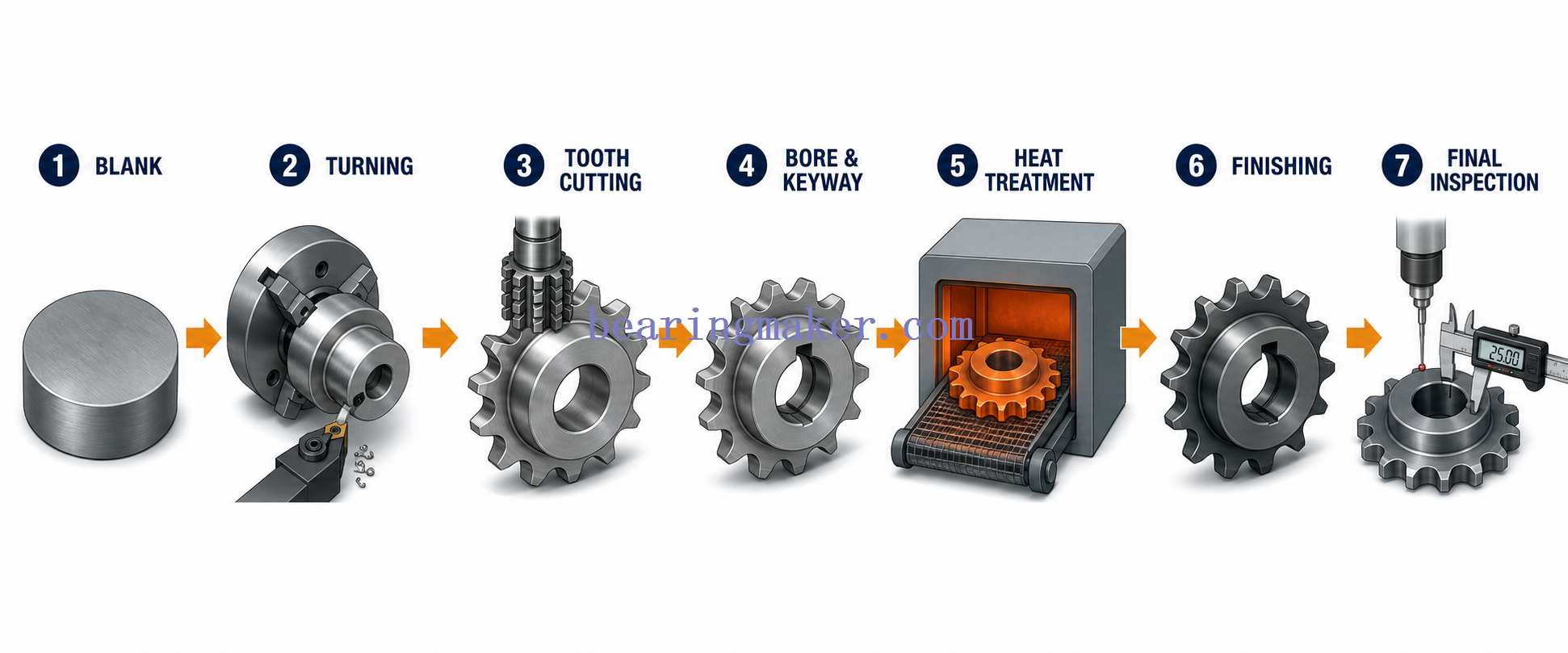
How Sprockets Are Manufactured
The manufacturing method depends on:
- sprocket diameter
- tooth count
- material
- production quantity
- required accuracy
- load
- cost target
A typical manufacturing route may include the following steps.
1. Blank Production
The initial sprocket blank may be produced by:
- bar-stock cutting
- plate cutting
- laser cutting
- forging
- casting
- stamping
2. Turning
Turning operations establish features such as:
- bore
- hub diameter
- faces
- shoulders
- concentric reference surfaces
3. Tooth Formation
Sprocket teeth may be generated using:
- hobbing
- milling
- specialized sprocket cutters
- CNC machining
- broaching or forming methods in suitable production processes
The selected process depends on sprocket size, geometry, material, quantity, and accuracy requirements.
4. Bore and Keyway Machining
The component may then receive:
- finished bore
- keyway
- set-screw holes
- mounting holes
- spline
- other shaft-interface features
5. Heat Treatment
Where additional wear resistance is required, processes may include:
- induction hardening
- through hardening
- carburizing
- other application-specific heat treatments
Tooth hardening can increase wear resistance while allowing the rest of the sprocket to retain different mechanical properties.
6. Surface Finishing
Depending on the environment, sprockets may receive:
- black oxide
- zinc coating
- phosphate coating
- nickel plating
- anodizing for aluminum
- other protective treatments
7. Inspection
Important inspection items may include:
- bore diameter
- bore-to-tooth concentricity
- face runout
- tooth geometry
- pitch accuracy
- keyway dimensions
- hub dimensions
- surface hardness
- material verification
For higher-speed systems, controlling runout and concentricity becomes increasingly important because geometric error can cause cyclic variation in chain tension.
How to Choose the Right Sprocket
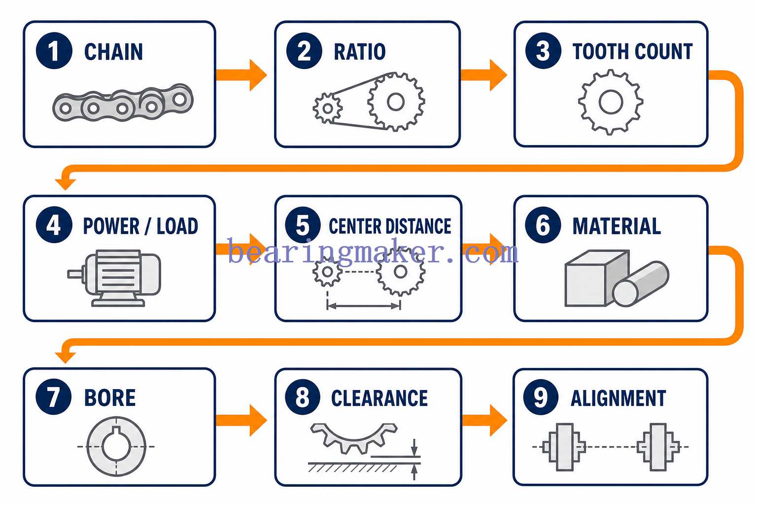
A reliable sprocket selection process should consider the entire drive system rather than selecting a sprocket by diameter alone.
Step 1: Identify the Chain
Start with the chain specification.
Check:
- chain standard
- chain pitch
- roller diameter
- inner width
- number of strands
- chain series
The sprocket must be manufactured specifically for a compatible chain.
Step 2: Determine the Required Ratio
Determine:
- input speed
- desired output speed
Then calculate the required ratio:
[
Ratio = \frac{Input\ Speed}{Output\ Speed}
]
The sprocket tooth-count ratio should provide approximately the same value.
For example:
Desired reduction:
[
1200\ rpm \rightarrow 400\ rpm
]
Required ratio:
[
1200/400 = 3:1
]
Possible sprocket combination:
- 18-tooth driver
- 54-tooth driven sprocket
because:
[
54/18 = 3
]
Step 3: Check the Small-Sprocket Tooth Count
Avoid choosing an unnecessarily small driving sprocket merely to obtain a large ratio.
A very small sprocket increases:
- articulation angle
- chordal action
- dynamic loading
- chain wear
Where practical, a small sprocket with approximately 17 or more teeth is often preferred in general-purpose roller-chain drives.
Step 4: Determine Power and Load
Evaluate:
- motor power
- shaft speed
- operating torque
- peak torque
- shock loads
- reversals
- starts and stops
- duty cycle
A conveyor starting fully loaded can require a significantly different drive from a continuously running lightly loaded machine, even when both use motors with similar nominal power.
Step 5: Consider the Service Factor
Real machinery rarely operates under perfectly steady conditions.
Applications involving:
- shock
- reciprocating loads
- frequent starting
- severe vibration
- long operating hours
may require a service factor above the nominal transmitted power.
The chain and sprocket system should therefore be sized for design power, not just motor nameplate power.
Step 6: Determine Shaft Center Distance
Chain drives can operate across greater distances than direct gear pairs, but center distance still affects performance.
A center distance that is too short can create:
- poor chain wrap
- difficult adjustment
- undesirable geometry
An excessively long unsupported chain span can create:
- sag
- vibration
- whipping
- poor tension control
Long drives may require:
- chain guides
- idlers
- tensioners
- intermediate support
Step 7: Select the Material
Choose material according to:
- load
- wear
- corrosion
- temperature
- weight
- hygiene requirements
- chemical exposure
For example:
| Environment | Typical Consideration |
|---|---|
| General industrial machine | Carbon or alloy steel |
| Corrosive washdown environment | Stainless steel |
| Lightweight mechanism | Aluminum |
| Quiet, lightly loaded machine | Engineering plastic |
| Severe wear or shock | Hardened or alloy steel |
Step 8: Select the Bore and Mounting Method
Verify:
- shaft diameter
- shaft tolerance
- key dimensions
- keyway
- set-screw location
- bushing system
- available hub length
- installation access
The chain may be correctly selected while the sprocket is still unusable if the shaft interface is wrong.
Step 9: Check Physical Clearance
Confirm:
- outside diameter
- hub diameter
- hub length
- chain width
- guard clearance
- frame clearance
- nearby bearings
- adjacent components
CAD interference checking is particularly useful in compact machinery.
Step 10: Verify Alignment
The driving and driven sprockets should operate in the same plane.
Poor alignment can cause:
- uneven tooth wear
- side-plate wear
- noise
- increased friction
- chain derailment
- shorter service life
ANSI and Metric Roller-Chain Sprockets
Two common roller-chain families are inch-series and metric-series chains.
Inch-Series Roller Chains
Common chain designations include sizes such as:
- 25
- 35
- 40
- 50
- 60
- 80
These designations correspond to specific dimensional standards rather than simply representing arbitrary model numbers.
Metric Roller Chains
Common metric-series designations include:
- 06B
- 08B
- 10B
- 12B
- 16B
These chains have their own standardized dimensional relationships.
Important
A sprocket should be selected against the complete chain specification, not simply by converting an inch pitch into millimeters.
Two chain systems with similar nominal pitch can still differ in:
- roller diameter
- inner width
- plate dimensions
- tooth-profile requirements
Sprocket Applications
Conveyor Systems
Sprockets are extensively used to drive conveyors in:
- warehouses
- factories
- packaging lines
- food-processing equipment
- distribution centers
- assembly systems
They provide repeatable mechanical synchronization and can operate across substantial machine lengths.
Motorcycles
A motorcycle final drive normally uses:
- a smaller front sprocket
- chain
- a larger rear sprocket
Changing tooth count changes the final-drive ratio.
For example, increasing rear sprocket tooth count while keeping the front sprocket unchanged generally provides:
- greater wheel torque
- stronger acceleration
- higher engine speed for a given road speed
- lower theoretical top speed at the same maximum engine rpm
The reverse occurs when the rear sprocket is made smaller.
Bicycles
Bicycle drivetrains use sprockets of different sizes to vary mechanical advantage.
Larger rear sprockets produce a lower gear, making climbing easier, while smaller rear sprockets provide a higher gear for greater speed per crank revolution.
Industrial Machinery
Chain drives are widely used in:
- packaging machines
- woodworking equipment
- agricultural machinery
- textile machinery
- printing machinery
- automated production equipment
They are especially useful where shafts are too far apart for direct gearing.
Construction and Tracked Equipment
Large drive sprockets can engage track links rather than conventional roller chains.
Applications include:
- excavators
- bulldozers
- tracked loaders
- other crawler machinery
These components operate under severe loads, contamination, shock, and abrasive conditions, so their geometry and materials differ considerably from light industrial roller-chain sprockets.
Timing and Indexing Systems
Chain-and-sprocket drives can also synchronize multiple shafts.
Applications may include:
- production machinery
- indexing equipment
- printing equipment
- packaging machines
- certain engine timing systems
For extremely precise positioning, however, system backlash, chain wear, elasticity, and polygonal action must be considered.
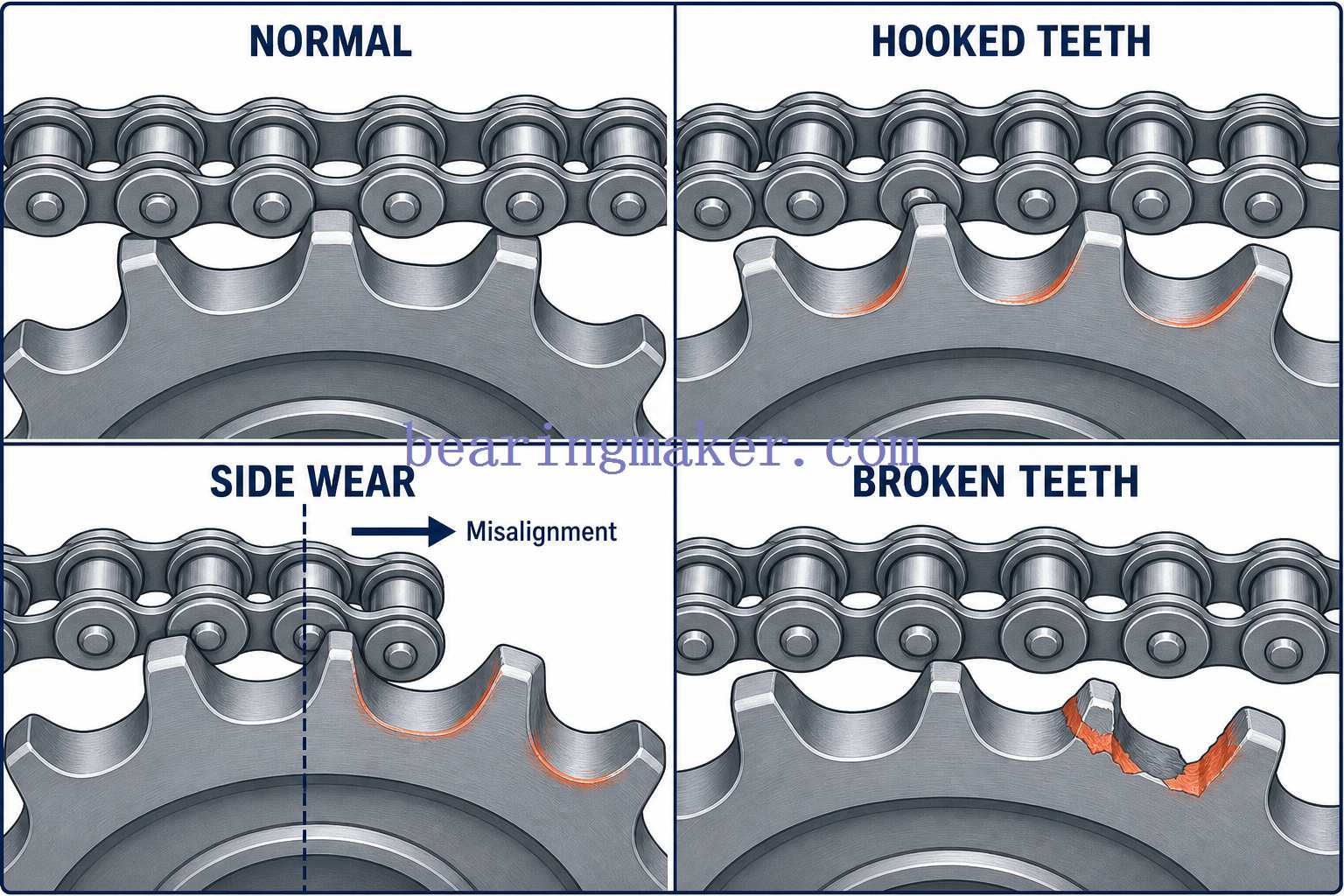
Common Sprocket Failure Modes
Understanding why sprockets fail is just as important as knowing how to select them.
1. Hooked Teeth
One of the most recognizable signs of sprocket wear is a tooth profile that begins to resemble a hook or wave.
Possible causes include:
- worn or elongated chain
- inadequate lubrication
- extended service life
- abrasive contamination
A heavily hooked sprocket should generally not be reused with a new chain.
2. Wear on One Side of the Teeth
Uneven side wear often indicates:
- sprocket misalignment
- shaft misalignment
- frame distortion
- incorrect positioning
Correcting lubrication alone will not solve an alignment problem.
3. Tooth Breakage
Broken teeth can result from:
- overload
- shock loading
- foreign-object intrusion
- inadequate material strength
- excessive hardness or brittleness
- poor installation
- severe chain wear
4. Excessive Noise
Noise may result from:
- insufficient lubrication
- excessive chain speed
- incorrect tension
- damaged sprocket teeth
- worn chain
- misalignment
- very small sprocket tooth count
- poor guarding or structure resonance
5. Chain Climbing or Poor Seating
If the chain does not seat correctly in the tooth pockets, possible causes include:
- severe chain elongation
- incompatible chain and sprocket
- worn sprocket teeth
- debris in tooth spaces
- improper tension
- dimensional damage
Sprocket Maintenance
Good sprocket life depends heavily on the condition of the chain.
Lubrication
Lubrication reduces friction between moving chain components and can also reduce wear at the sprocket interface.
The correct lubricant depends on:
- chain type
- speed
- temperature
- contamination
- operating environment
Applying lubricant only to the outer surface of the chain may be insufficient because the most critical lubrication points are often within the chain joints.
Alignment
Check whether the sprocket faces operate in the same plane.
For long drives, even small angular or parallel misalignment can become significant.
Chain Tension
A chain should generally not be tensioned like a rigid belt.
Excessive tension can increase loads on:
- chain pins
- bushings
- sprockets
- bearings
- shafts
Too much slack can lead to:
- vibration
- chain whipping
- poor engagement
- derailment
The appropriate sag or tension depends on the drive layout and chain-system recommendations.
When Should a Sprocket Be Replaced?
Inspect the sprocket whenever the chain is being serviced or replaced.
Replacement should be considered if there is:
- visible hooking of teeth
- severe tooth thinning
- chipped or cracked teeth
- excessive side wear
- damaged keyway or bore
- excessive runout
- severe corrosion
- poor engagement with a new chain
A new chain operating on severely worn sprockets may rapidly develop abnormal wear because the worn tooth profile no longer matches the geometry of the new chain.
For this reason, chain and sprocket condition should be evaluated as a system, rather than treating each component independently.
Chain Elongation and Sprocket Wear
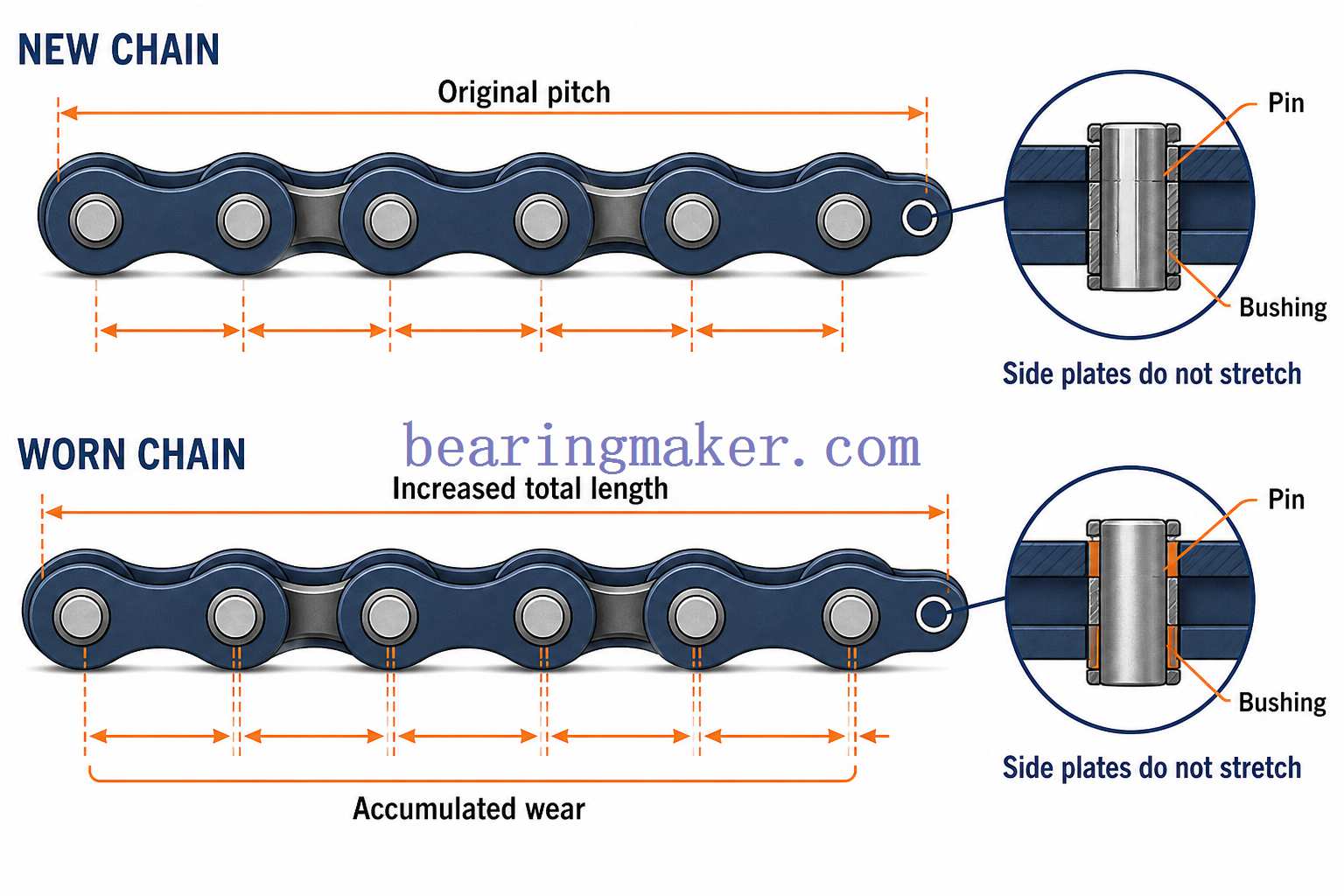
A roller chain does not normally become longer because its steel plates physically stretch.
Most apparent chain “stretch” is caused by wear at:
- pins
- bushings
- bearing surfaces
As these interfaces wear, the effective pitch of the chain gradually increases.
This is properly called:
chain elongation due to wear.
The acceptable elongation limit depends on the application.
Systems requiring accurate synchronization may require replacement at a much smaller percentage of elongation than slow, non-critical conveyor drives.
Therefore, a universal percentage should not be used for every chain system.
Common Sprocket Selection Mistakes
Mistake 1: Selecting by Outside Diameter
Two sprockets with similar outside diameters can have different:
- pitch
- tooth count
- chain compatibility
Always start with the chain specification.
Mistake 2: Ignoring Roller Diameter and Chain Series
Matching pitch does not necessarily guarantee compatibility.
Check the full chain dimensions.
Mistake 3: Choosing Too Few Teeth
A very small driving sprocket may reduce package size but can increase:
- chordal action
- articulation
- vibration
- wear
Mistake 4: Oversizing Chain Tension
Overtightening can increase bearing and shaft loads without improving power transmission.
Mistake 5: Ignoring Alignment
Good chain tension cannot compensate for misaligned sprockets.
Mistake 6: Installing a New Chain on Severely Worn Sprockets
The mismatch between new-chain pitch and worn-tooth geometry can accelerate wear.
Mistake 7: Selecting Material Based Only on Strength
A strong carbon-steel sprocket may still be unsuitable in a corrosive washdown environment.
Selection should include environmental conditions.
Sprocket Selection Checklist
Before ordering or designing a sprocket, verify the following:
| Item | What to Check |
|---|---|
| Chain standard | Inch, metric, conveyor, engineering, specialty |
| Chain size | Complete chain designation |
| Pitch | Must correspond to sprocket |
| Strand count | Simplex, duplex, triplex, etc. |
| Tooth count | Ratio, diameter, chordal action |
| Input speed | rpm |
| Output speed | Required rpm |
| Power | Motor and design power |
| Torque | Continuous and peak |
| Duty cycle | Continuous, intermittent, reversing |
| Environment | Corrosion, dust, chemicals, washdown |
| Material | Steel, stainless, aluminum, plastic, etc. |
| Bore | Shaft diameter and tolerance |
| Keyway | Required size |
| Hub | Space and mounting requirements |
| Center distance | Shaft spacing |
| Alignment | Shaft and sprocket plane |
| Lubrication | Method and lubricant |
| Clearance | OD, width, guards, housing |
This information is normally sufficient to narrow the available sprocket designs significantly.
Frequently Asked Questions
What Is a Sprocket?
A sprocket is a toothed wheel designed to engage a chain, track, or similar positively driven element. In a roller-chain system, its teeth engage the chain rollers to transmit rotational motion and power between shafts.
Is a Sprocket the Same as a Gear?
No.
A gear normally meshes directly with another gear, while a sprocket engages a chain.
Sprockets are therefore particularly useful when power must be transmitted between shafts separated by a significant distance.
Is a Sprocket a Pulley?
No.
A pulley normally transfers force through a belt, rope, or cable.
A sprocket uses positive tooth engagement with a chain or similar element.
Can Sprockets Slip?
Under normal operating conditions, a correctly matched roller chain and sprocket do not experience the continuous frictional slip associated with belt drives.
However, severe wear, excessive slack, damaged teeth, incorrect components, or derailment can cause the chain to climb or jump teeth.
What Determines Sprocket Speed Ratio?
The ratio is determined by the tooth counts of the driving and driven sprockets.
For a simple two-sprocket drive:
[
\frac{Output\ Speed}{Input\ Speed}
\frac{Driver\ Teeth}{Driven\ Teeth}
]
Does a Larger Sprocket Increase Torque?
If the driven sprocket becomes larger while the driving sprocket remains unchanged, output speed decreases and theoretical output torque increases.
The opposite occurs when the driven sprocket becomes smaller.
How Many Teeth Should a Sprocket Have?
There is no single correct tooth count for every application.
For many general-purpose roller-chain drives, designers prefer around 17 teeth or more on the smaller sprocket where practical because additional teeth reduce chordal action and chain articulation.
Compact, slow-speed, or specialized systems may use fewer teeth.
What Is the Difference Between Simplex, Duplex, and Triplex Sprockets?
They refer to the number of chain strands:
- Simplex: one chain strand
- Duplex: two parallel strands
- Triplex: three parallel strands
Multiple strands are used when greater power capacity is required without moving to a much larger chain pitch.
What Material Is Best for a Sprocket?
There is no universal best material.
Typical choices include:
- carbon steel for general industrial machinery
- hardened or alloy steel for heavy wear and high loads
- stainless steel for corrosive environments
- aluminum for weight-sensitive applications
- engineering plastics for lightly loaded, quiet, or corrosion-resistant systems
Is a Sprocket the Same as a Bearing?
No.
A sprocket transmits motion and torque, while a bearing supports a shaft or rotating component and reduces friction between moving surfaces.
They are frequently used together.
For example, an idler sprocket may contain a bearing in its center so that the sprocket can rotate freely around a stationary shaft.
Why Do Sprocket Teeth Become Hook-Shaped?
Hook-shaped teeth usually develop because repeated chain engagement gradually wears one side of the tooth profile.
This often becomes worse when operating with an elongated chain.
Severely hooked sprockets should normally be replaced rather than paired with a new chain.
Should the Chain and Sprockets Be Replaced Together?
Not necessarily in every case, but all components should be inspected together.
If the sprocket tooth profile is significantly worn, installing a new chain alone can produce poor engagement and accelerated wear.
In high-duty systems, replacing worn chains and sprockets as a matched maintenance set can sometimes be more economical than replacing components individually.
Conclusion
A sprocket may appear to be a simple toothed wheel, but its performance depends on the interaction of several factors:
- chain pitch
- roller dimensions
- tooth count
- speed ratio
- sprocket diameter
- material
- hub and bore configuration
- shaft alignment
- center distance
- lubrication
- chain condition
The most important rule is to treat the chain and sprockets as one transmission system.
Start by identifying the exact chain, determine the required speed and torque ratio, select suitable tooth counts, and then evaluate load, material, shaft mounting, center distance, environmental conditions, and maintenance requirements.
A properly selected sprocket does more than transmit power. It helps reduce vibration, distribute wear, maintain synchronization, protect the chain, and improve the reliability and service life of the entire drive system.
