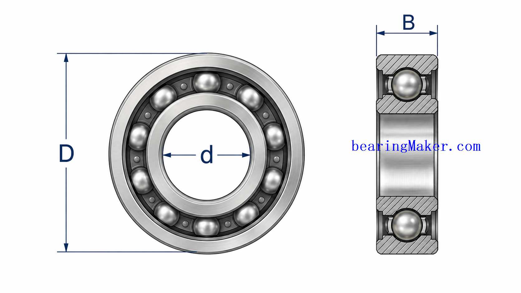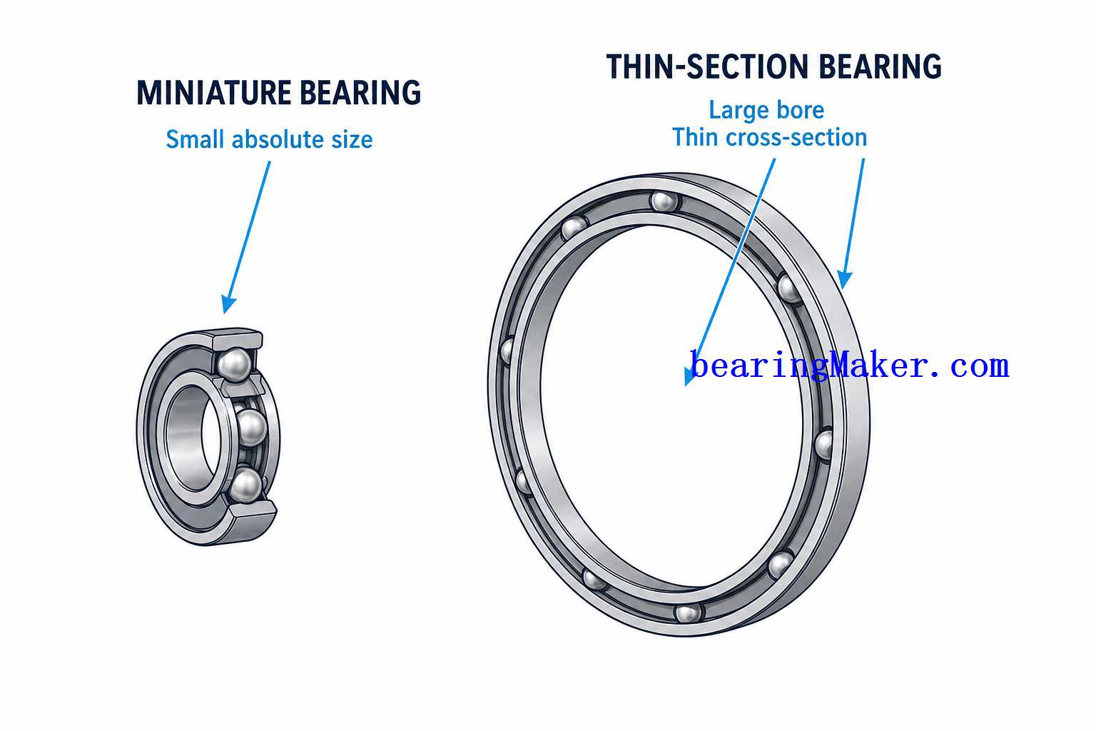
Miniature bearings are used in compact mechanisms where loads may appear small in absolute terms.
A small electric motor may carry only a light rotor.
A cooling fan may apply only modest radial force.
An encoder shaft may experience almost no heavy external load.
Yet miniature bearings can still fail from overload, poor load distribution, shock, shaft deflection, or incorrect preload.
The reason is simple:
small bearings also have small rolling elements, small raceways, and small contact areas.
A force that seems insignificant in a large industrial bearing may represent a substantial load relative to the geometry of a miniature bearing.
For this reason, miniature bearing selection should not be based only on:
- bore
- outside diameter
- speed
The load condition must also be understood.
A reliable design should consider:
- radial load
- axial load
- combined load
- dynamic load
- static load
- shock
- preload
- shaft deflection
- housing alignment
- operating duty cycle
This guide explains how miniature bearings carry load, how load capacity is rated, how basic bearing life is estimated, and why actual service life may differ significantly from the calculated value.
How Miniature Bearings Carry Load
Most miniature bearings are deep groove ball bearings.
Their load path is:
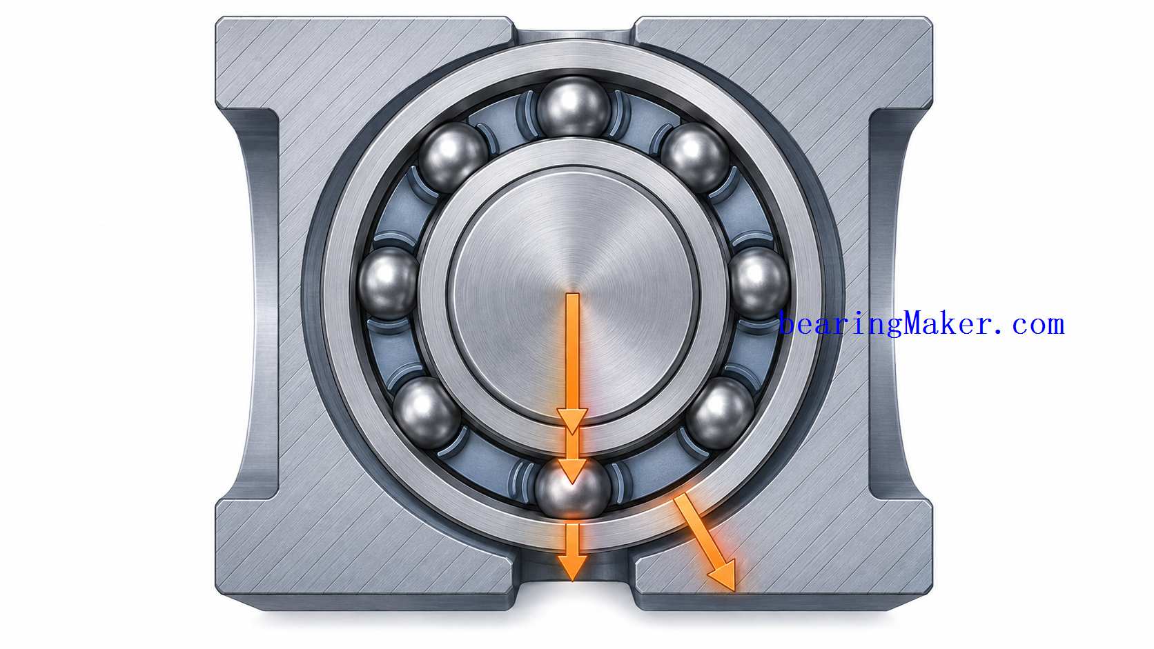
shaft → inner ring → balls → outer ring → housing
The balls transfer force through very small contact zones between the rolling elements and raceways.
These contacts are highly stressed even when the external force is relatively modest.
Load distribution depends on:
- radial clearance
- axial clearance
- preload
- raceway geometry
- shaft alignment
- housing alignment
Not every ball carries the same load at the same time.
Main Load Types
Miniature bearings typically experience:
- radial load
- axial load
- combined load
Some applications may also experience:
- shock
- oscillation
- reversing loads
- moment effects from shaft bending
Radial Load
Radial load acts perpendicular to the shaft axis.
Common sources include:
- rotor weight
- belt tension
- gear forces
- fan imbalance
- impeller load
- pulley force
Deep groove miniature ball bearings are well suited to radial load.
Radial Load Distribution
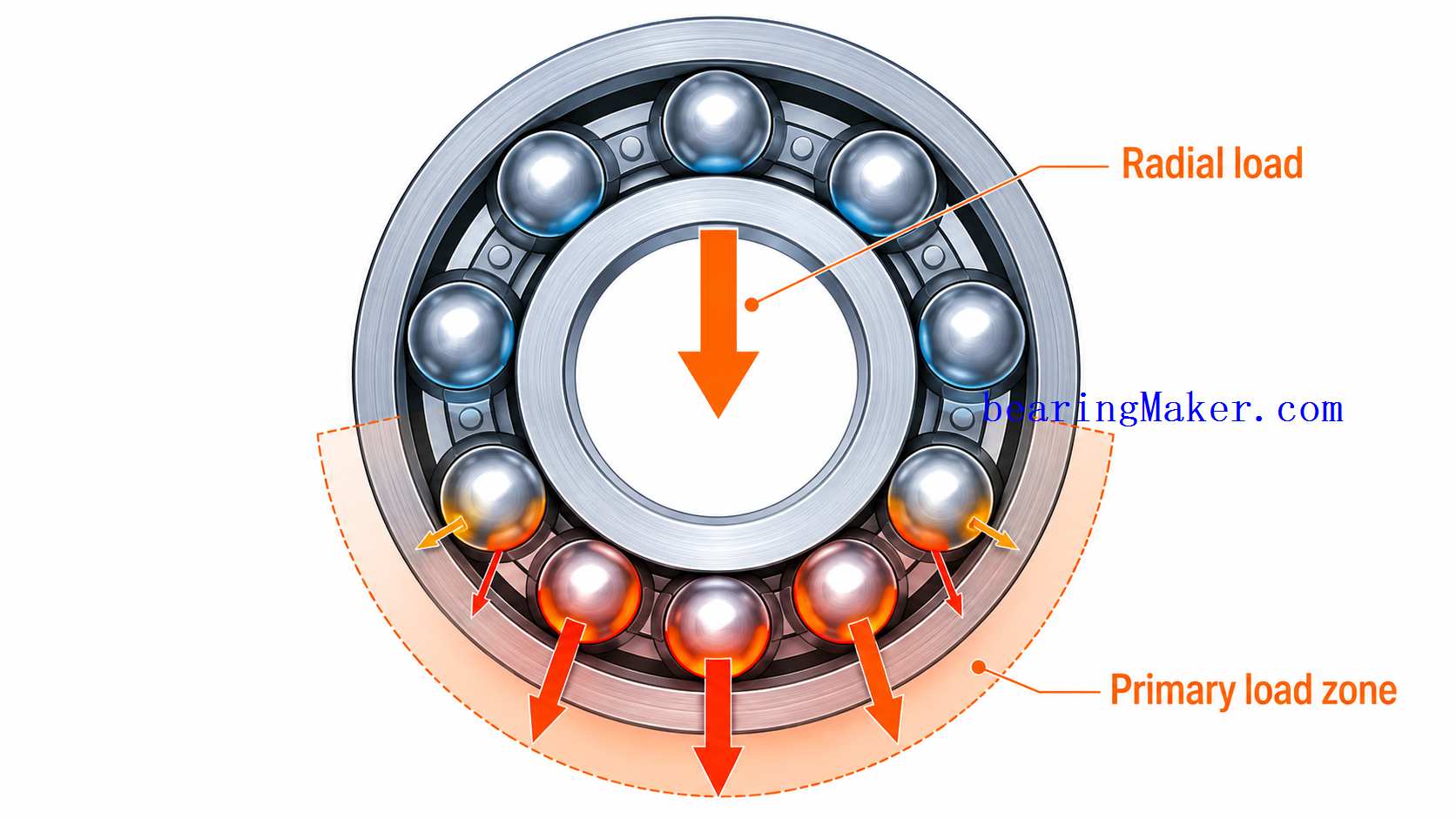
Under radial load, the balls in the primary load zone carry most of the force.
Balls near the opposite side of the bearing may carry very little load.
The exact distribution depends on:
- clearance
- preload
- deformation
This means it is incorrect to assume:
total radial load ÷ number of balls = load per ball
The real load distribution is uneven.
Axial Load
Axial load acts parallel to the shaft axis.
Possible sources include:
- impeller thrust
- helical gears
- springs
- actuators
- vertical rotor weight
Deep groove miniature bearings can usually carry some axial load in either direction.
However, their axial capability is not unlimited.
Why Deep Groove Bearings Can Carry Axial Load
The deep raceway geometry allows the ball contact angle to shift when axial force is applied.
This creates an axial reaction force.
As thrust increases:
- contact angle changes
- internal contact stress increases
If axial load becomes too large, another bearing type or arrangement may be more appropriate.
Combined Load
Combined loading occurs when radial and axial loads act simultaneously.
This is very common in:
- miniature pumps
- gear drives
- small motors
- actuators
The bearing does not experience these loads independently.
They combine into an equivalent internal load condition.
Equivalent Dynamic Bearing Load
For fatigue calculations, combined radial and axial loads are often converted into an equivalent dynamic bearing load.
A general form is:
P=XFr+YFaP = XF_r + YF_a
where:
- PP = equivalent dynamic bearing load
- FrF_r = radial load
- FaF_a = axial load
- XX and YY = bearing-specific factors
The exact values depend on:
- bearing geometry
- load ratio
- internal clearance
They should be taken from the relevant bearing data.
Why You Should Not Simply Add Radial and Axial Load
A simple expression such as:
P=Fr+FaP = F_r + F_a
does not necessarily represent the real internal bearing load.
The contact geometry determines how the bearing reacts to combined loading.
This is particularly important when axial force becomes a significant percentage of radial load.
Dynamic Load Rating
The basic dynamic load rating is commonly represented by:
CC
It is used in rolling-contact fatigue life calculations.
Dynamic load rating should not be interpreted as:
- maximum allowable instantaneous load
- ultimate failure load
- static capacity
It is a standardized fatigue-related rating.
Why Dynamic Load Rating Matters
The dynamic rating allows engineers to compare bearing fatigue capability.
For the same equivalent load:
- a bearing with higher CC
- generally provides longer calculated fatigue life
Basic Bearing Life
For ball bearings, the basic rating life relationship is:
L10=(CP)3L_{10}= \left(\frac{C}{P}\right)^3
where:
- L10L_{10} = basic rating life in millions of revolutions
- CC = basic dynamic load rating
- PP = equivalent dynamic load
This relationship shows how strongly bearing life depends on load.
What Does L10 Mean?
L10 is a statistical bearing life concept.
It represents the number of revolutions that 90% of a sufficiently large population of apparently identical bearings are expected to reach or exceed under specified conditions.
It does not mean:
- every bearing will fail at exactly that point
- actual machine life is guaranteed
Converting Bearing Life to Hours
If rotational speed is known:
L10h=10660n(CP)3L_{10h}= \frac{10^6}{60n} \left(\frac{C}{P}\right)^3
where:
- L10hL_{10h} = life in hours
- nn = speed in rpm
Example Life Calculation
Suppose a miniature bearing has:
- dynamic load rating C=1,000 NC = 1,000\text{ N}
- equivalent dynamic load P=250 NP = 250\text{ N}
- speed n=6,000 rpmn = 6,000\text{ rpm}
First:
CP=1000250=4\frac{C}{P}= \frac{1000}{250}=4
Then:
L10=43=64L_{10}=4^3=64
So:
L10=64 million revolutionsL_{10}=64\text{ million revolutions}
Convert to hours:
L10h=64×10660×6000L_{10h}= \frac{64\times10^6}{60\times6000} L10h≈178 hoursL_{10h}\approx178\text{ hours}
This example shows why very high speed can convert a large number of revolutions into a relatively modest number of operating hours.
Why Small Load Changes Matter So Much
For ball bearings:
L10∝1P3L_{10}\propto \frac{1}{P^3}
This means life is highly sensitive to load.
If equivalent load doubles, theoretical life decreases dramatically.
If equivalent load is cut in half, theoretical life increases by a factor of:
23=82^3=8
This is why accurate load estimation is important.
Miniature Bearings and High Speed
Miniature bearings often operate at very high rpm.
High speed does not directly increase the equivalent load in the basic life equation, but it affects:
- number of stress cycles per hour
- temperature
- lubrication
- cage behavior
This means a bearing with a high revolution life may still accumulate those revolutions quickly.
Static Load Rating
The basic static load rating is commonly represented by:
C0C_0
It relates to permanent deformation at the rolling-element contact under stationary or very slow loading.
Static rating becomes important when the bearing experiences:
- impact
- shock
- high stationary load
- assembly force
Why Static Load Is Especially Important in Miniature Bearings
Miniature bearings have small rolling elements and raceways.
An impact that would appear minor in a larger mechanism can create permanent indentation.
Examples include:
- dropping a component
- pressing the bearing incorrectly
- hammering during assembly
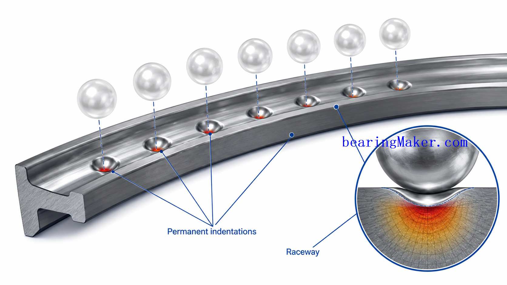
Brinelling
Permanent raceway indentations caused by excessive static or impact load are often associated with brinelling.
Symptoms may include:
- periodic vibration
- noise
- rough rotation
Once the raceway is permanently indented, the bearing cannot return to its original precision.
Static Safety Factor
A static safety factor may be written as:
s0=C0P0s_0=\frac{C_0}{P_0}
where:
- s0s_0 = static safety factor
- C0C_0 = static load rating
- P0P_0 = equivalent static bearing load
The required safety factor depends on:
- shock
- vibration
- precision requirements
Dynamic vs. Static Load
These two should always be checked separately.
Dynamic Check
Answers:
Will repeated rolling contact provide sufficient fatigue life?
Static Check
Answers:
Will high stationary or impact loading permanently damage the contact surfaces?
A design can pass one and fail the other.
Shock Loads
Miniature bearings may experience shock during:
- assembly
- shipping
- product drops
- rapid machine stops
- tool impact
Shock load may be much higher than normal operating load.
Why Normal Operating Load Is Not Enough
Consider a miniature motor that normally carries only a small rotor load.
During shipping, an impact may create a force many times higher than the normal running load.
The bearing may become damaged before the machine is first switched on.
Installation Load
Installation is one of the most common opportunities to overload a miniature bearing.
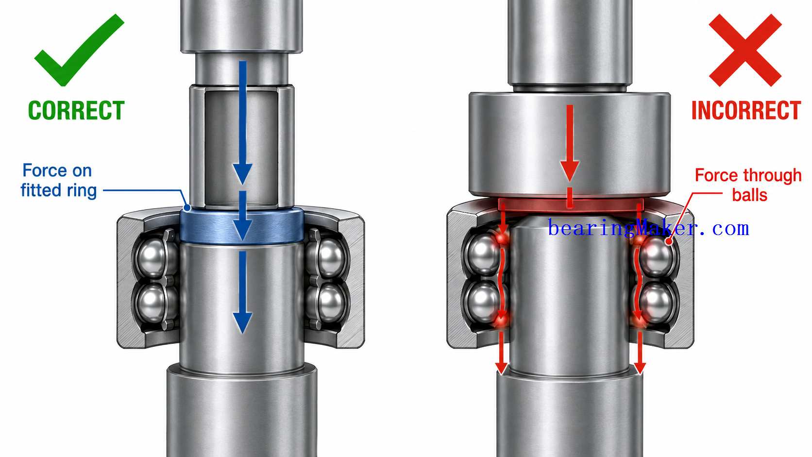
If the inner ring has the interference fit, force should generally be applied directly to the inner ring.
If the outer ring has the interference fit, force should be applied to the outer ring.
Why Pressing Through the Balls Is Dangerous
If installation force passes through the rolling elements, the balls can press into the raceways.
This can create permanent dents.
Preload Is Also an Internal Load
Preload is intentionally applied to reduce clearance and improve stiffness.
But preload increases rolling-element contact force.
This means preload contributes to:
- bearing stress
- friction
- heat
Why Preload Is Used
Miniature bearing preload may be used in:
- precision instruments
- encoders
- motor shafts
to reduce:
- axial play
- vibration
- positioning variation
Too Much Preload
Excess preload can cause:
- high running torque
- overheating
- reduced fatigue life
- lubricant stress
A small bearing can be particularly sensitive because the available torque budget is often very low.
Preload vs. Life
Increasing preload may improve:
- stiffness
- precision
but can reduce:
- fatigue life
- speed capability
The correct preload is therefore a compromise.
Internal Clearance and Load Distribution
Internal clearance affects how many balls carry load.
With larger clearance:
- fewer balls may initially carry the load
With preload:
- more rolling elements may remain engaged
This changes:
- stiffness
- peak ball load
- friction
Shaft Deflection
One of the most important miniature-bearing system issues is shaft deflection.
Miniature bearings are often installed on very small shafts.
The shaft may bend under:
- belt load
- gear load
- overhung weight
Why Shaft Deflection Matters
If the shaft bends, the inner ring may tilt relative to the outer ring.
This can create:
- uneven ball loading
- higher contact stress
- reduced life
The bearing may have sufficient catalog load capacity while the shaft still creates poor load distribution.
Example of an Overhung Load
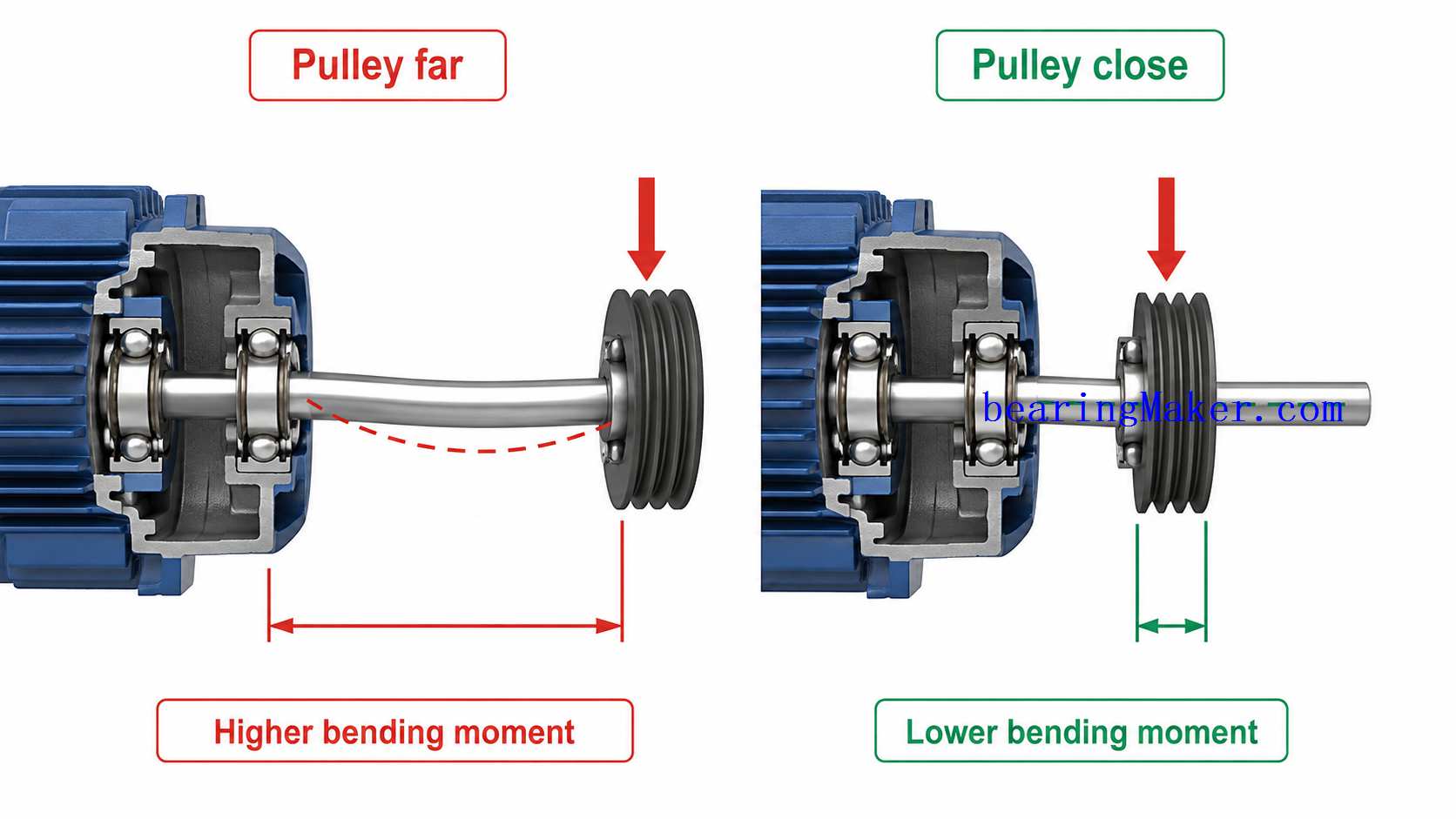
Suppose a pulley is mounted some distance away from the bearing.
The pulley force creates:
- radial bearing load
- shaft bending moment
Moving the pulley closer to the bearing can reduce:
- shaft deflection
- bearing load
without changing the bearing itself.
Bearing Spacing
Two miniature bearings are often used to support one shaft.
The distance between them influences shaft stability.
Increasing bearing spacing can improve resistance to:
- tilting
- moment load
within packaging limits.
Closely Spaced Bearings
Very small spacing may create a compact assembly but reduce the effective support span.
This may increase shaft angular movement.
Wider Bearing Spacing
Greater spacing generally improves:
- shaft stability
- moment resistance
but increases machine length.
Housing Alignment
Two bearing seats must be sufficiently aligned.
If they are not coaxial, the bearings may be forced into misalignment.
This can create:
- additional load
- heat
- reduced life
Why Small Bearings Are Sensitive to Misalignment
Miniature deep groove bearings are not automatically self-aligning.
Because dimensions are small, a minor absolute alignment error can be significant relative to:
- bearing width
- internal clearance
Combined Bearing and Shaft System
The real system should therefore be evaluated as:
bearing + shaft + housing
rather than the bearing alone.
Load Distribution Between Two Bearings
When two bearings support a shaft, the load is distributed according to:
- force location
- bearing spacing
- shaft stiffness
If the load is centered between two identical supports, the load may be shared relatively evenly.
If the load is overhung, the load on one bearing can become much larger.
Overhung Load Example
For a shaft supported by two bearings, an external load beyond one bearing can create:
- high reaction load on the near bearing
- opposite reaction at the other bearing
The bearing nearest the external load may carry much more than the applied force itself.
This is why simple “external force = bearing load” assumptions can be wrong.
Moment Loads in Miniature Systems
Miniature bearings are not usually selected primarily for large overturning moments in the same way as large thin section bearings.
However, shaft moments still matter.
Typical sources include:
- overhung gears
- pulleys
- fans
- impellers
Moment effects are usually handled by:
- bearing spacing
- shaft stiffness
- two-bearing arrangements
Oscillating Motion
Some miniature bearings do not rotate continuously.
They may oscillate through a small angle.
Examples include:
- miniature actuators
- instrument pivots
- scanning mechanisms
Why Oscillation Can Be Difficult
Small-angle oscillation may repeatedly load the same raceway region.
Lubricant may not redistribute effectively.
This can contribute to:
- fretting
- false brinelling
- localized wear
A bearing selected only from continuous-rotation life calculations may not fully represent this condition.
Reversing Motion
Repeated reversing can influence:
- cage dynamics
- lubricant distribution
- load zones
This is relevant in:
- small actuators
- robotics
- indexing mechanisms
Variable Loads
Many miniature bearing applications do not operate at constant load.
A motor may experience:
- startup load
- steady load
- acceleration
- shutdown
Duty Cycle
The bearing should be evaluated across the actual duty cycle.
High-load periods may contribute disproportionately to fatigue.
An average load alone may hide these peaks.
Why Peak Load Matters
Because fatigue life is strongly nonlinear with load, a short high-load event can have a much larger effect than its percentage of operating time suggests.
Load Spectrum
A simple load spectrum may include:
- idle
- normal operation
- acceleration
- peak load
Each should be considered separately when loads vary significantly.
Lubrication and Load Capacity
Lubrication does not change the catalog dynamic load rating itself, but inadequate lubrication can reduce real service life.
Poor lubrication can cause:
- surface wear
- increased friction
- heat
- premature fatigue
Contamination and Bearing Life
Contamination is especially dangerous in miniature bearings.
A particle that seems microscopic at machine scale can be relatively large compared with:
- ball contact
- raceway curvature
It can create:
- dents
- scratches
- stress concentrations
Why Clean Assembly Matters
Contamination may enter during:
- assembly
- lubrication
- storage
Clean handling can significantly improve actual bearing life.
Temperature and Bearing Life
Temperature affects:
- lubricant viscosity
- internal clearance
- material dimensions
High temperature can reduce lubricant life and increase:
- wear
- friction
Low Temperature
Low temperature may increase lubricant viscosity.
This can raise:
- starting torque
- rolling resistance
In small motors, the result may prevent reliable startup.
Fits and Bearing Load
Tight fits change the internal geometry of the bearing.
An excessive inner-ring fit may reduce clearance.
An excessive outer-ring fit may also reduce clearance.
The bearing may become unintentionally preloaded.
Fit-Induced Load
If interference is too great, the bearing can experience internal contact load even before external forces are applied.
This should be considered in precision or low-torque applications.
Plastic Housings and Load Distribution
Miniature bearings are often installed in plastic housings.
These can deform under:
- load
- temperature
- long-term creep
This may affect:
- outer-ring support
- alignment
- load distribution
Bearing Life vs. Actual Service Life
Calculated L10 life is useful, but actual field life depends on many additional conditions.
These include:
- lubrication
- contamination
- temperature
- fits
- alignment
- shaft deflection
- shock
Why a Bearing Can Fail Before Its L10 Life
A bearing may fail early because of:
- contamination
- poor lubrication
- brinelling
- installation damage
These failure modes are not simply normal rolling fatigue.
Why a Bearing Can Last Longer Than L10
L10 is statistical.
Some bearings may operate significantly longer under favorable conditions.
It is not a fixed expiration point.
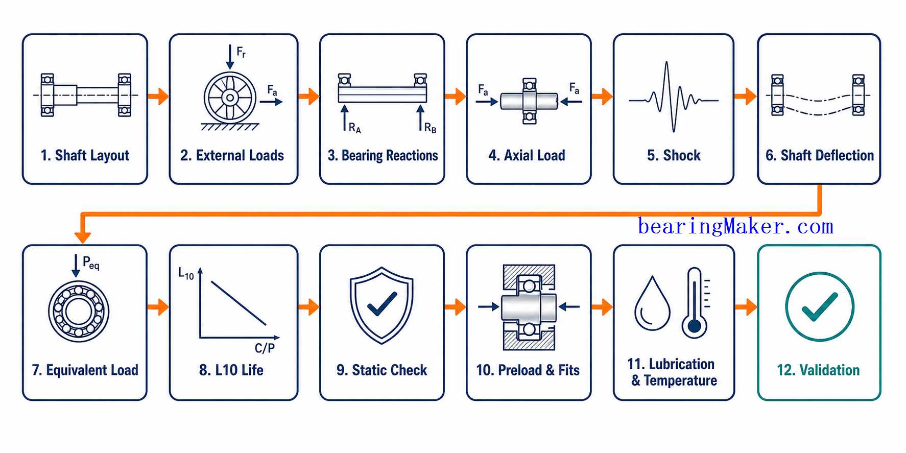
Practical Bearing Load Analysis Workflow
Step 1: Define the Shaft Layout
Determine:
- bearing locations
- spacing
- external load locations
Step 2: Identify All External Forces
Include:
- rotor weight
- belt force
- gear force
- spring force
- impeller force
Step 3: Calculate Radial Bearing Reactions
Determine how external loads are divided between the bearings.
Step 4: Determine Axial Load
Identify thrust from:
- gears
- pumps
- actuators
Step 5: Include Shock and Peak Loads
Consider:
- startup
- emergency stop
- drops
- transport
Step 6: Evaluate Shaft Deflection
Check whether the small shaft bends excessively.
Step 7: Determine Equivalent Dynamic Load
Use the appropriate radial/axial load relationship for the bearing.
Step 8: Calculate L10 Life
Use:
L10=(CP)3L_{10}= \left(\frac{C}{P}\right)^3
Step 9: Convert Life to Hours
Use operating speed to calculate expected hours.
Step 10: Check Static Capacity
Include:
- impact
- stationary load
- installation load
Step 11: Include Preload
Account for intentional or fit-induced internal load.
Step 12: Check Fits
Verify that shaft and housing interference do not create excessive preload.
Step 13: Evaluate Lubrication and Temperature
Confirm the bearing can maintain suitable lubrication under real operating conditions.
Step 14: Evaluate Contamination
Check whether:
- shields
- seals
- clean assembly
are required.
Step 15: Validate Actual Operating Condition
Monitor:
- temperature
- vibration
- torque
- noise
after assembly.
Example: Small Electric Motor
Consider a small motor with:
- two miniature bearings
- rotor located between the bearings
- moderate operating speed
The bearing loads may come from:
- rotor weight
- magnetic imbalance
- shaft imbalance
Even if the static load is small, high speed creates a large number of fatigue cycles.
Important checks include:
- dynamic life
- shaft alignment
- lubrication
- vibration
Example: Cooling Fan
A cooling fan may have:
- small radial load
- high operating hours
- high speed
In this application, actual service life may be controlled more by:
- lubricant life
- contamination
- temperature
than by basic load capacity.
Example: Miniature Pump
A miniature pump may create:
- radial impeller load
- axial hydraulic thrust
The bearing should be checked for:
- combined load
- corrosion
- sealing
Example: Encoder Shaft
An encoder may carry very little external load.
The main concerns may instead be:
- preload
- low torque
- runout
In this case, a larger load rating does not necessarily improve the design.
Common Load and Life Calculation Mistakes
Mistake 1: Assuming Small External Load Means Bearing Load Is Negligible
The bearing itself is small, so relative contact stress can still be significant.
Mistake 2: Ignoring Axial Load
Small impellers and gears can generate meaningful thrust.
Mistake 3: Using External Force Directly as Bearing Load
Bearing reactions depend on shaft geometry and load location.
Mistake 4: Ignoring Overhung Loads
A pulley or gear outside the bearing span can create high bearing reaction loads.
Mistake 5: Ignoring Shaft Deflection
The shaft may fail stiffness requirements before the bearing reaches its load limit.
Mistake 6: Checking Dynamic Life but Not Static Load
Installation or shock can damage the bearing even if L10 is high.
Mistake 7: Ignoring Preload
Preload adds internal rolling-element stress.
Mistake 8: Using Average Load Only
Short peak loads may contribute strongly to fatigue or static damage.
Mistake 9: Assuming L10 Equals Actual Life
Real life also depends on:
- contamination
- lubrication
- temperature
Mistake 10: Ignoring Installation Force
A new bearing may be damaged before operation begins.
Load and Life Selection Matrix
| Operating Condition | Primary Check |
|---|---|
| Continuous rotation | Dynamic rating + L10 |
| Very high RPM | L10 hours + lubrication |
| Stationary heavy load | Static rating |
| Impact/shock | Static safety |
| Combined radial + axial | Equivalent dynamic load |
| Overhung pulley | Bearing reactions + shaft deflection |
| High preload | Internal stress + torque |
| Small oscillation | Fretting / lubrication |
| Plastic housing | Alignment + fit stability |
| Dirty environment | Contamination control |
Troubleshooting Short Bearing Life
If a miniature bearing fails earlier than expected, check:
- actual load
- shaft alignment
- preload
- lubrication
- contamination
- installation damage
Troubleshooting Raceway Indentations
Likely causes include:
- impact
- incorrect installation
- static overload
Troubleshooting High Torque
Possible causes include:
- excessive preload
- excessive interference
- viscous lubricant
- contact seals
Troubleshooting Repeated Failures
If the replacement bearing fails in the same way, investigate the system rather than assuming bearing quality alone is the cause.
Check:
- shaft geometry
- housing alignment
- actual load
- installation process
Frequently Asked Questions
How Much Load Can a Miniature Bearing Carry?
Load capacity depends on:
- bearing size
- ball size
- raceway geometry
Always use the actual dynamic and static load ratings for the selected bearing.
Can Miniature Bearings Carry Axial Loads?
Yes.
Deep groove miniature bearings can generally carry some axial load in both directions.
The allowable thrust depends on the specific design.
What Is Dynamic Load Rating?
Dynamic load rating CC is used in basic rolling-fatigue life calculations.
What Is Static Load Rating?
Static load rating C0C_0 relates to permanent deformation under heavy stationary or impact loading.
What Is L10 Bearing Life?
L10 is the basic rating life that 90% of a sufficiently large population of apparently identical bearings is expected to reach or exceed under specified conditions.
How Do I Calculate Miniature Bearing Life?
For ball bearings:
L10=(CP)3L_{10}= \left(\frac{C}{P}\right)^3
is the basic starting equation.
Why Does Bearing Life Drop So Quickly as Load Increases?
Because ball-bearing life varies approximately with the inverse cube of equivalent load.
Can a Miniature Bearing Fail Even With a Very Small Load?
Yes.
Possible causes include:
- high speed
- poor lubrication
- contamination
- installation damage
- preload
Can Installation Damage Reduce Bearing Life?
Yes.
Pressing through the rolling elements can create permanent raceway damage.
Does Preload Reduce Bearing Life?
Excessive preload increases internal contact stress and can reduce fatigue life.
Does Shaft Bending Affect Bearing Life?
Yes.
Shaft deflection can create misalignment and uneven rolling-element loading.
Do All Balls Carry the Same Load?
No.
The load is distributed unevenly among the rolling elements.
Why Does Bearing Spacing Matter?
Greater spacing between two bearings can improve shaft stability and reduce angular movement.
Are L10 Calculations Accurate for Oscillating Motion?
They are useful as a reference, but small-angle oscillation may introduce other issues such as:
- false brinelling
- localized lubrication problems
Can Contamination Reduce Bearing Life?
Yes.
Small particles can indent miniature bearing raceways and create local stress concentrations.
Can Temperature Affect Bearing Load?
Yes.
Temperature can change:
- clearance
- fit
- lubricant viscosity
and therefore alter the real internal load condition.
Miniature Bearing Load Selection Checklist
Before finalizing a miniature bearing, define:
| Parameter | What to Determine |
|---|---|
| Shaft layout | Bearing positions and spacing |
| Radial load | Continuous and peak |
| Axial load | Magnitude and direction |
| Overhung load | Distance from bearing |
| Bearing reactions | Load on each support |
| Shock | Expected peak |
| Static load | Stationary condition |
| Dynamic rating | CC |
| Static rating | C0C_0 |
| Equivalent dynamic load | PP |
| Equivalent static load | P0P_0 |
| L10 life | Revolutions |
| L10 hours | At operating rpm |
| Preload | Internal load |
| Internal clearance | Installed condition |
| Shaft stiffness | Deflection |
| Bearing spacing | Adequate |
| Housing alignment | Coaxiality |
| Shaft fit | Correct interference |
| Housing fit | Correct interference |
| Speed | Continuous and peak |
| Lubrication | Suitable for speed/load |
| Temperature | Operating range |
| Contamination | Protection required |
| Installation load | Controlled |
| Duty cycle | Normal/peak/reversing |
Conclusion
Miniature bearing load analysis is not simply a matter of finding a bearing whose catalog load rating exceeds the external force.
Small bearings operate with:
- small rolling elements
- small raceways
- small shafts
so relatively modest forces can create significant contact stress or shaft deflection.
A complete design must consider:
- radial load
- axial load
- combined load
- shock
- static load
- preload
- shaft deflection
- bearing spacing
The basic dynamic-life relationship:
L10=(CP)3L_{10}= \left(\frac{C}{P}\right)^3
is an important starting point, but it does not describe every real-world failure mechanism.
Actual service life also depends on:
- lubrication
- contamination
- temperature
- fits
- alignment
- installation
The most reliable selection sequence is:
Shaft Layout → External Loads → Bearing Reactions → Radial/Axial Load → Shock → Shaft Deflection → Equivalent Load → L10 Life → Static Safety → Preload → Fits → Lubrication → Operating Validation
The goal is not merely to select a miniature bearing that can carry the nominal load.
The goal is to create a small rotating system in which the bearing, shaft, housing, lubrication, and installation all allow the bearing to maintain:
- sufficient life
- low friction
- low vibration
- stable temperature
- reliable operation
throughout the actual duty cycle of the machine.