
Thrust bearings are designed for one of the most important jobs in rotating machinery: controlling axial force and preventing unwanted movement along a shaft.
They are found in gearboxes, pumps, compressors, machine tools, automotive transmissions, marine propulsion systems, industrial drives, turbines, actuators, and countless other machines where rotation generates force parallel to the shaft axis.
A thrust bearing may look simple, but selecting the wrong design can lead to:
- excessive axial movement
- overheating
- lubricant breakdown
- abnormal vibration
- raceway damage
- gear or impeller misalignment
- premature bearing failure
- damage to surrounding components
This guide explains what thrust bearings are, how they work, the major types available, how they compare, how to size and select them, and what installation and maintenance factors have the greatest influence on service life.
What Is a Thrust Bearing?
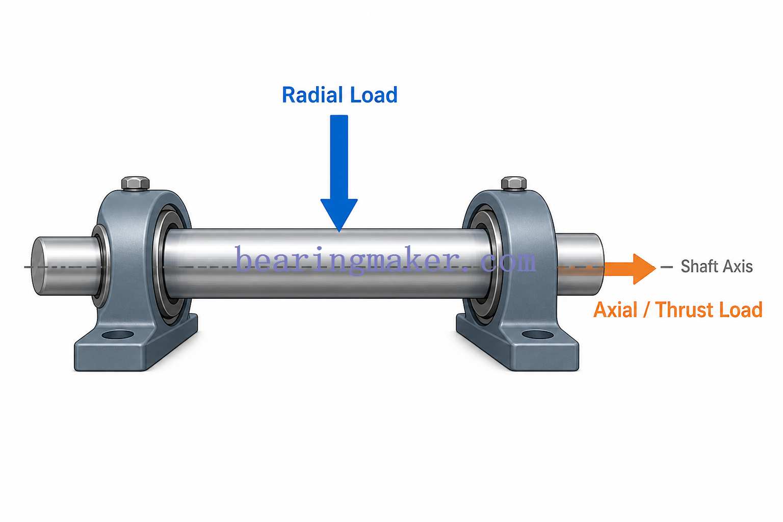
A thrust bearing is a bearing designed primarily to support axial load, meaning force acting parallel to the axis of rotation.
If a shaft is considered horizontal:
- a radial load pushes up, down, or sideways across the shaft
- an axial or thrust load pushes along the length of the shaft
Thrust bearings prevent the shaft or rotating component from moving excessively in that axial direction.
Common Sources of Axial Load
Axial force can be created by many machine elements, including:
- helical gears
- bevel gears
- centrifugal pumps
- propellers
- screw compressors
- extruder screws
- lead screws
- turbines
- clutches
- vertical shafts
For example, a helical gear generates an axial force because its teeth are angled. A centrifugal pump may develop hydraulic thrust along its shaft. A marine propeller pushes the vessel forward while simultaneously pushing the propeller shaft backward into its thrust-bearing system.
The bearing must safely transfer these forces into the machine housing or supporting structure.
Why Thrust Bearings Are Different from Radial Bearings
Radial and thrust bearings are not interchangeable simply because they both contain balls or rollers.
Their raceway geometry and internal load paths are designed differently.
Radial Bearings
Radial bearings are optimized primarily for forces acting perpendicular to the shaft.
Examples include:
- deep groove ball bearings
- cylindrical roller bearings
- needle roller bearings
Some radial bearings can also support moderate axial force.
Thrust Bearings
Dedicated thrust bearings are optimized primarily for force parallel to the shaft.
Examples include:
- thrust ball bearings
- cylindrical roller thrust bearings
- needle roller thrust bearings
- spherical roller thrust bearings
Many conventional flat-raceway thrust bearings should not be subjected to meaningful radial load.
Combined-Load Bearings
Some bearing designs occupy the middle ground and are intentionally designed for both radial and axial loads.
Examples include:
- angular contact ball bearings
- tapered roller bearings
These are frequently selected when a machine does not have separate radial and thrust bearings.
How Does a Thrust Bearing Work?
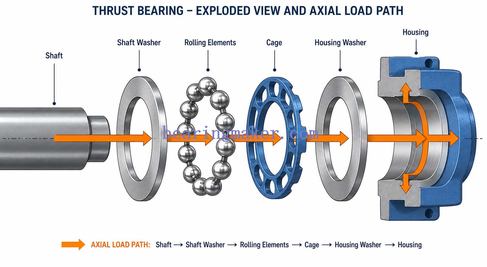
A thrust bearing creates a controlled load path between a rotating shaft and a stationary machine structure.
In a basic thrust bearing:
- The shaft generates axial force.
- A shaft washer or bearing ring receives that force.
- Balls or rollers transmit it through rolling contact.
- A stationary washer or ring transfers the load into the housing.
- The housing transfers the load into the machine structure.
Rolling elements reduce friction compared with direct sliding contact and allow the shaft to rotate while remaining axially constrained.
The Importance of Raceway Geometry
The ability of a bearing to carry thrust is determined largely by the orientation of the contact between:
- rolling elements
- inner raceway
- outer raceway
A flat thrust ball bearing directs force almost completely along the axial direction.
An angular contact bearing uses inclined raceways, allowing the contact force to contain both:
- radial component
- axial component
A tapered roller bearing achieves a similar combined-load capability using tapered rollers.
This explains why bearing geometry is more important than simply asking whether a bearing contains “balls” or “rollers.”
Single-Direction vs. Double-Direction Thrust Bearings
One of the first decisions in thrust-bearing selection is whether axial force acts in one direction or both.
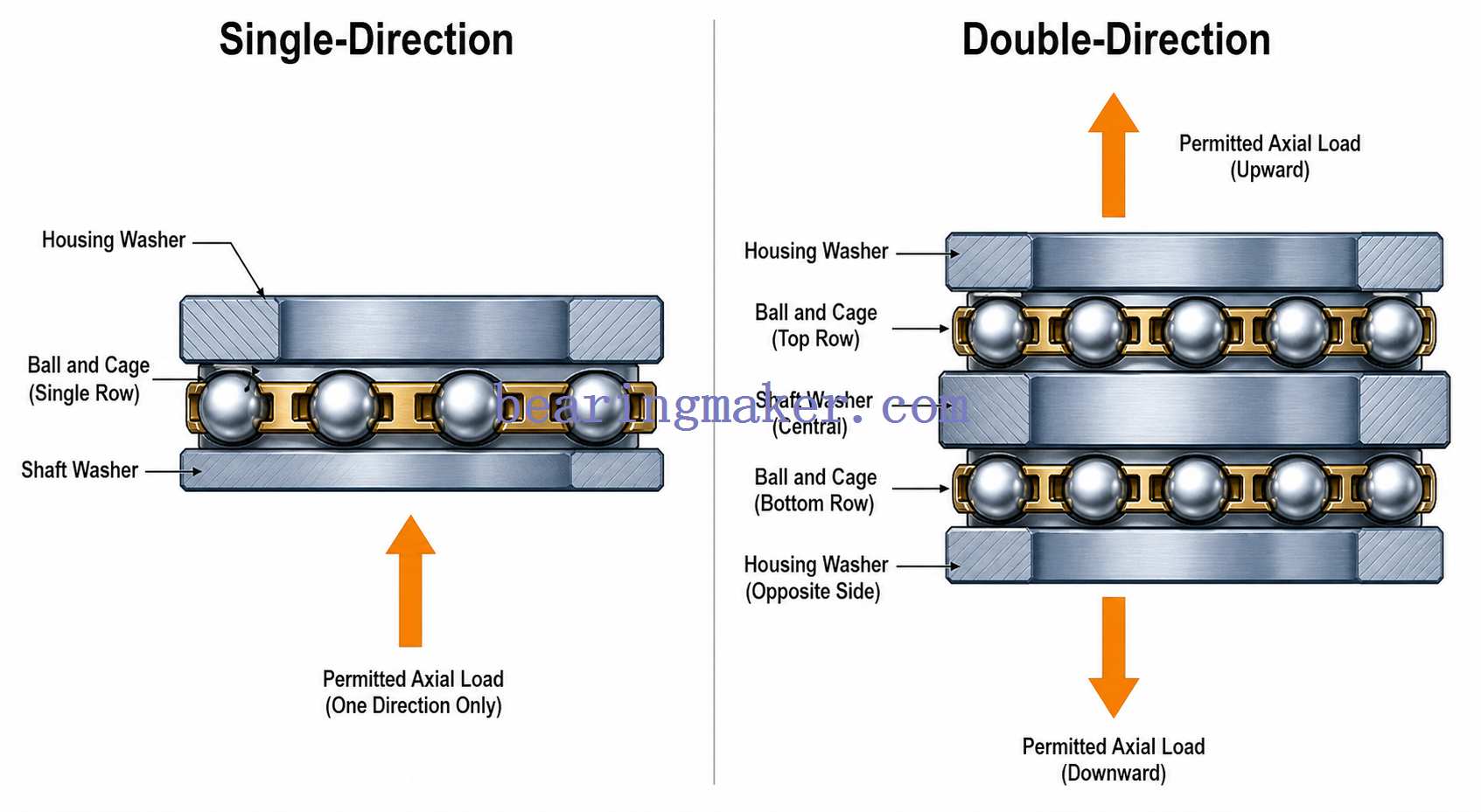
Single-Direction Thrust Bearings
These support axial force in one direction.
A typical thrust ball bearing includes:
- shaft washer
- housing washer
- ball-and-cage assembly
They can locate a shaft axially in one direction.
If thrust reverses, another bearing or locating arrangement is required.
Double-Direction Thrust Bearings
These support axial forces in both directions.
A typical double-direction ball thrust bearing uses:
- one central shaft washer
- two housing washers
- two ball-and-cage assemblies
These arrangements are useful where axial force reverses during operation.
Main Types of Thrust Bearings
Different thrust-bearing designs prioritize different characteristics.
| Bearing Type | Axial Load Capacity | Radial Load Capability | Speed Capability | Misalignment Capability | Typical Strength |
|---|---|---|---|---|---|
| Thrust ball bearing | Low–Moderate | Very limited / none | High | Low | Low friction |
| Angular contact ball bearing | Moderate–High | Yes | High–Very high | Low | Combined loads and precision |
| Needle roller thrust bearing | High for size | Very limited | Moderate | Low | Minimal axial space |
| Cylindrical roller thrust bearing | High | Very limited | Moderate | Low | High axial rigidity |
| Spherical roller thrust bearing | Very high | Some radial load | Low–Moderate | High | Heavy load + misalignment |
| Tapered roller bearing | High–Very high | Yes | Moderate | Low | Heavy combined loads |
These values are general tendencies rather than fixed ratings. Actual capability depends on bearing size, internal design, lubrication, cage construction, load, and operating conditions.
1. Thrust Ball Bearings
Thrust ball bearings use balls between grooved washers or bearing rings.
They are generally selected for:
- pure or predominantly axial loads
- moderate load levels
- relatively high rotational speeds
- applications where low friction is important
Advantages
- low rolling friction
- relatively high speed capability
- simple construction
- compact axial arrangement
- accurate axial location
- broad size availability
Limitations
- lower load capacity than comparable roller thrust bearings
- poor tolerance for misalignment
- conventional designs are unsuitable for meaningful radial load
- mounting surfaces must be accurately square to the shaft axis
Single-Direction Thrust Ball Bearings
These support axial force in only one direction.
Typical uses include:
- valve mechanisms
- vertical shafts
- machine mechanisms
- rotating tables
- light industrial machinery
Double-Direction Thrust Ball Bearings
These support axial load in both directions.
They are useful in systems where:
- load direction reverses
- shaft location must be controlled from either side
Miniature Thrust Ball Bearings
Miniature versions provide axial support where installation space is very limited.
Applications can include:
- instrumentation
- optical equipment
- miniature actuators
- small electromechanical mechanisms
- laboratory equipment
At small sizes, cleanliness, shaft accuracy, and mounting precision become especially important.
2. Angular Contact Ball Bearings
Angular contact ball bearings are not conventional flat thrust bearings, but they are extremely important in applications requiring simultaneous axial and radial load support.
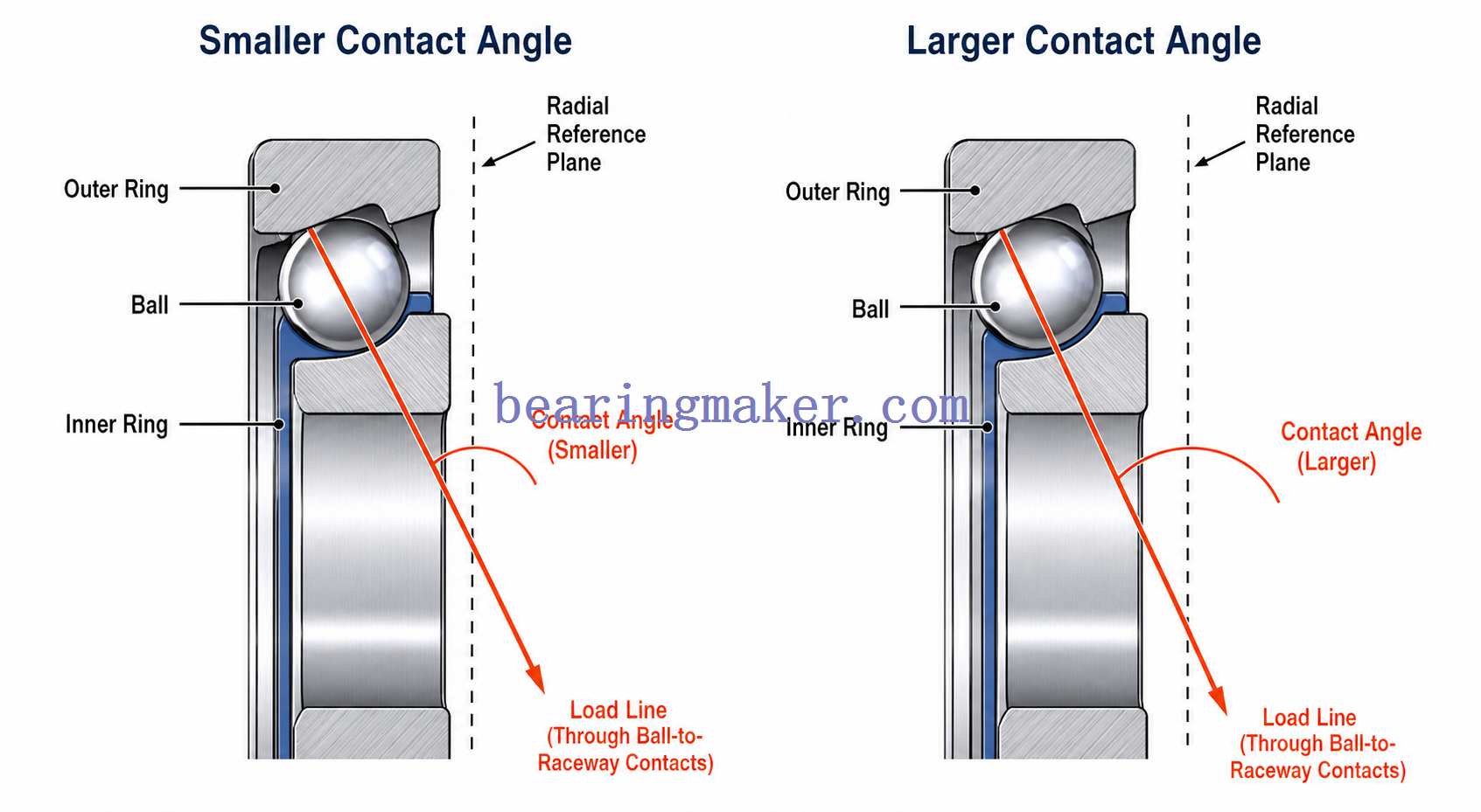
Their raceways are offset so that the contact force acts at a contact angle.
Common contact angles vary by design.
In general:
- smaller contact angle → favors higher speed and radial capability
- larger contact angle → increases axial-load capability
Why Contact Angle Matters
Imagine a line connecting the points where a ball contacts the inner and outer raceways.
That line forms an angle with the radial plane.
The larger this angle becomes, the greater the proportion of load the bearing can transmit axially.
Common Applications
- centrifugal pumps
- machine-tool spindles
- compressors
- precision gearboxes
- electric spindles
- high-speed equipment
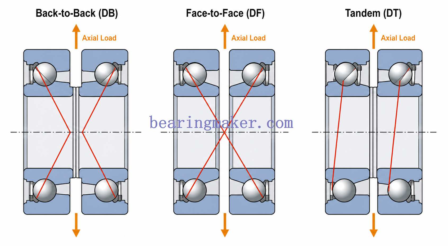
Paired Angular Contact Bearings
One angular contact bearing normally supports significant axial load primarily in one direction.
To support thrust in both directions, bearings may be installed as matched pairs.
Back-to-Back Arrangement
The load lines diverge outward.
Advantages include:
- high moment rigidity
- good shaft-location capability
- strong resistance to overturning moments
Face-to-Face Arrangement
The load lines converge inward.
Advantages can include:
- somewhat greater tolerance for certain alignment conditions
- compact effective load-center spacing
Tandem Arrangement
Both bearings face the same direction.
This arrangement increases axial load capacity in one direction.
A separate opposing bearing may be required for reverse thrust.
3. Needle Roller Thrust Bearings
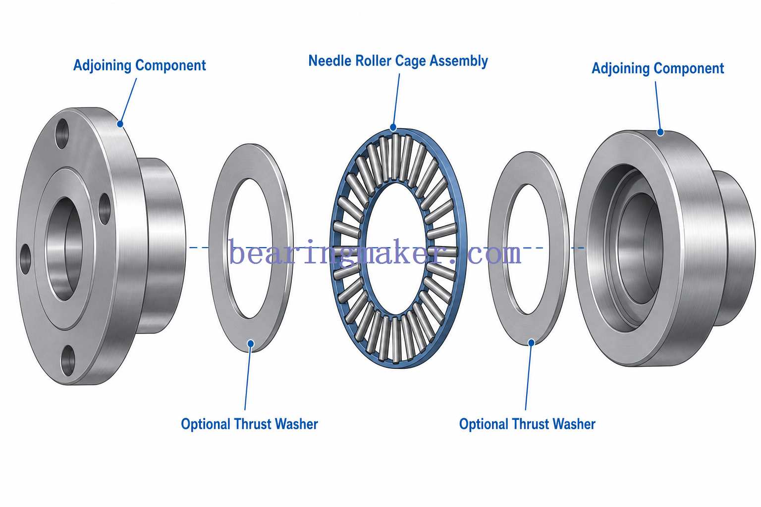
Needle roller thrust bearings use long, small-diameter cylindrical rollers arranged radially around the bearing axis.
Their greatest advantage is high axial capacity within a very small axial height.
They are particularly useful when axial packaging space is limited.
Advantages
- very small axial cross-section
- high load capacity relative to package height
- high stiffness
- low mass
- compact design
Common Applications
- automatic transmissions
- planetary gear systems
- compact gearboxes
- machine mechanisms
- clutches
- industrial drives
Raceway Requirements
Some needle thrust assemblies consist only of:
- needle rollers
- cage
The surrounding machine components may act directly as raceways.
When this approach is used, the mating surfaces must provide appropriate:
- hardness
- flatness
- surface finish
- dimensional accuracy
If the machine components cannot provide suitable raceway surfaces, separate thrust washers should be used.
4. Cylindrical Roller Thrust Bearings
Cylindrical roller thrust bearings use short cylindrical rollers positioned to carry axial load.
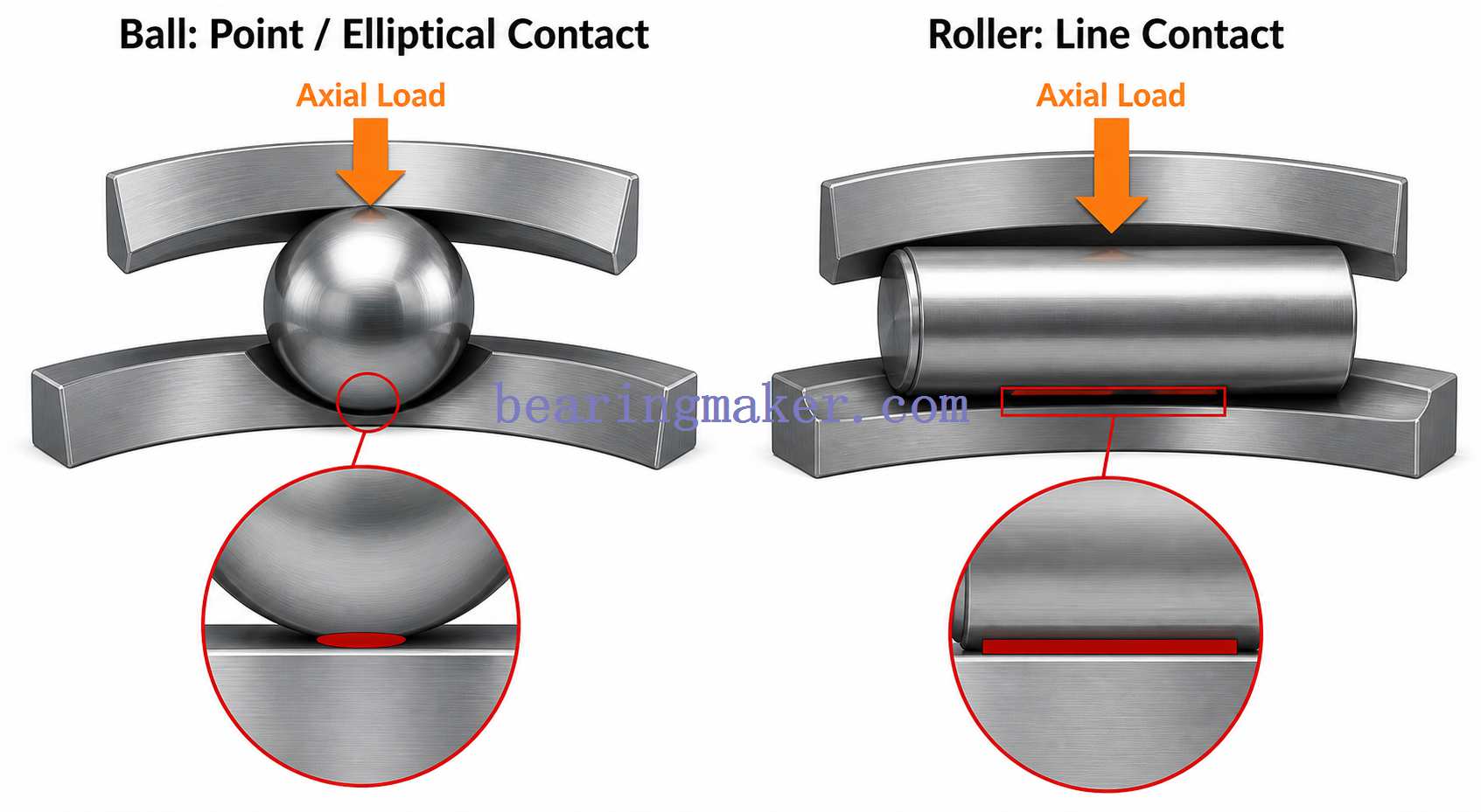
The line contact between rollers and raceways gives them greater load capacity and rigidity than ball thrust bearings of comparable size.
Advantages
- high axial-load capacity
- high axial stiffness
- good resistance to shock loading
- compact design for heavy-load applications
Limitations
- limited radial-load capability
- sensitive to misalignment
- sliding occurs internally because different parts of a roller travel at different circumferential speeds
- speed capability is generally lower than that of thrust ball bearings
Typical Applications
- heavy industrial gearboxes
- machine presses
- rolling equipment
- large mechanical drives
- low-to-moderate-speed heavy machinery
5. Spherical Roller Thrust Bearings
Spherical roller thrust bearings are among the most capable thrust-bearing designs for heavy industrial equipment.
They use:
- asymmetrical barrel-shaped rollers
- inclined raceways
- spherical housing raceway geometry
This allows them to carry very high axial loads while accommodating a degree of shaft-to-housing misalignment.
They can also carry some radial load when axial load is simultaneously present, subject to the bearing design and operating conditions.
Main Advantages
- very high axial-load capacity
- high stiffness
- tolerance of angular misalignment
- ability to accommodate shaft deflection
- suitability for shock and heavy-duty service
Common Applications
- large gearboxes
- extrusion equipment
- heavy industrial drives
- marine propulsion
- mining machinery
- pulp and paper machinery
- vertical shafts
- large process equipment
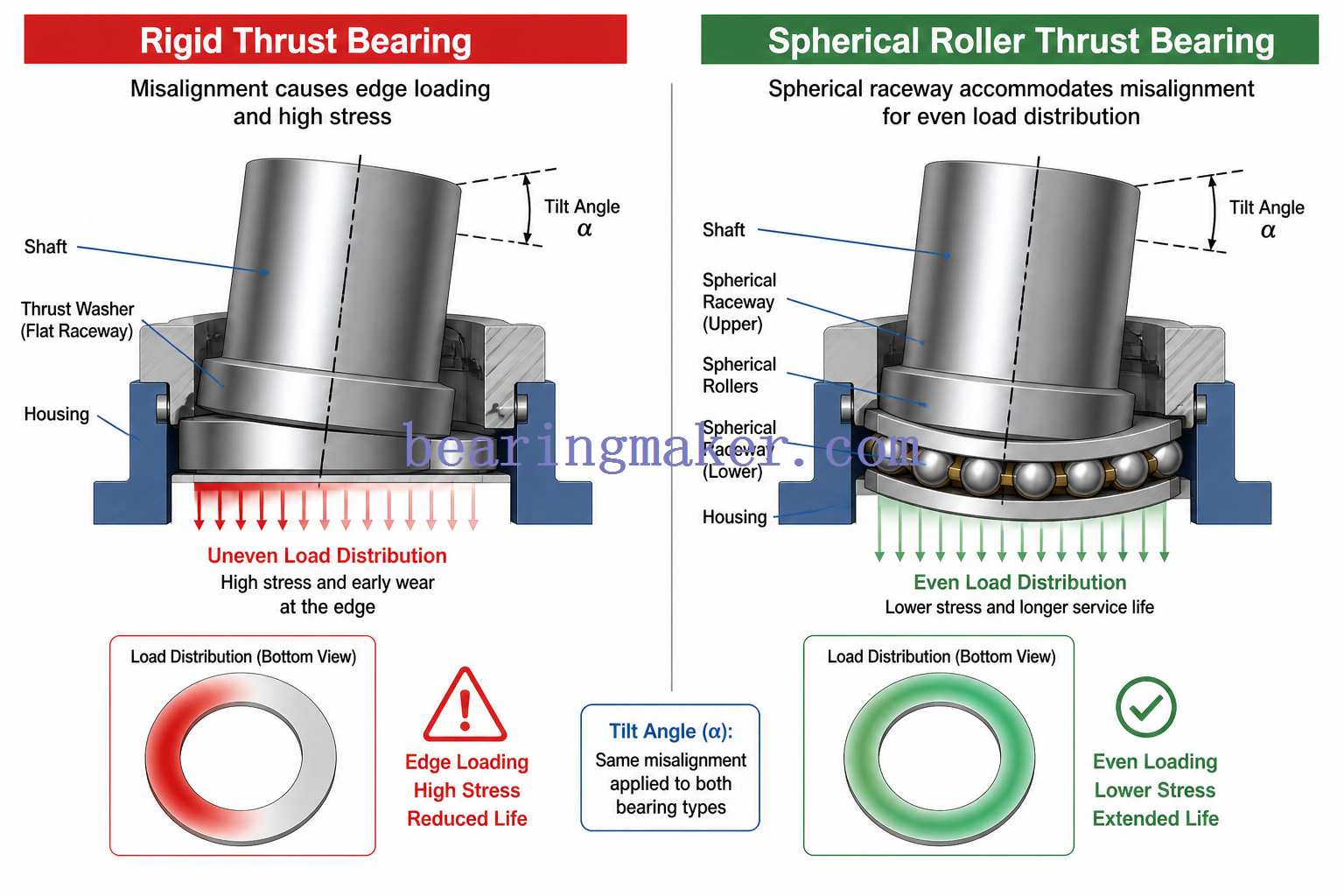
Why Self-Alignment Matters
Large machinery is rarely perfectly rigid.
Under heavy load:
- shafts bend
- housings deform
- foundations move
- temperature changes geometry
A rigid thrust bearing may experience strong edge loading under these conditions.
A spherical roller thrust design can redistribute contact as the shaft angle changes within the bearing’s permissible alignment range.
6. Tapered Roller Bearings for Thrust Loads
Tapered roller bearings support both radial and axial loads using tapered raceways and tapered rollers.
Although they are not always classified as dedicated thrust bearings, they are one of the most important solutions for heavy combined loads.
Their geometry directs rolling-element contact toward a common apex on the shaft axis.
Advantages
- high radial capacity
- high axial capacity
- high rigidity
- effective shaft positioning
- suitable for heavy combined loads
Common Applications
- vehicle wheel ends
- differentials
- industrial gearboxes
- bevel gear shafts
- agricultural machinery
- construction equipment
Adjustment and Preload
Tapered roller bearings are often installed in opposing pairs.
Their operating clearance or preload must be controlled carefully.
Too much clearance can cause:
- poor shaft positioning
- vibration
- reduced gear accuracy
Too much preload can cause:
- high friction
- excessive temperature
- lubricant degradation
- reduced service life
Ball vs. Roller Thrust Bearings
A useful first-level comparison is the contact geometry.
Ball Bearings
Balls provide relatively small contact areas.
Typical consequences:
- lower friction
- higher speed
- lower load capacity
- lower rigidity
Roller Bearings
Rollers produce larger contact areas.
Typical consequences:
- greater load capacity
- greater stiffness
- better heavy-load performance
- somewhat higher friction
- lower maximum speed
Thrust Bearings by Application
Gearboxes
Helical and bevel gears produce axial forces naturally.
Possible bearing choices include:
- angular contact ball bearings
- tapered roller bearings
- cylindrical roller thrust bearings
- spherical roller thrust bearings
Selection depends on:
- gear size
- thrust magnitude
- shaft speed
- required rigidity
Centrifugal Pumps
Hydraulic forces can push the pump shaft axially.
Common solutions include:
- paired angular contact bearings
- other combined-load bearing arrangements
Bearing selection must account for operating conditions such as:
- normal running
- startup
- shutdown
- changes in flow
- transient hydraulic forces
Automotive Transmissions
Transmissions often have severe packaging constraints.
Needle roller thrust bearings are particularly useful because they can fit between:
- gears
- clutch components
- planetary assemblies
while occupying very little axial space.
Marine Propulsion
Propeller thrust creates a continuous axial reaction on the propulsion shaft.
Large marine systems may therefore require heavy-duty thrust-bearing arrangements capable of:
- high sustained axial load
- shaft movement
- structural deflection
- continuous operation
Machine Tools
Machine tools require more than simple load capacity.
Important characteristics include:
- axial rigidity
- low runout
- thermal stability
- preload control
- high rotational accuracy
Precision angular contact bearing arrangements are commonly used in spindle systems.
Extruders
Extruder screws generate very high axial forces while turning relatively slowly.
Heavy-duty roller thrust bearings are often preferred because:
- thrust load is high
- rigidity is important
- extremely high speed is not required
Vertical Shafts
When a shaft is vertical, component weight itself creates a continuous axial load.
Examples include:
- vertical pumps
- rotary tables
- large rotating equipment
The bearing arrangement must support both:
- working thrust
- gravitational load
How to Choose the Right Thrust Bearing
The correct selection process begins with the machine requirements.
Do not start with bore diameter alone.
Step 1: Determine Load Direction
Ask:
Does thrust act in one direction or both?
One-direction load may use:
- single-direction thrust bearing
- single angular contact bearing
- tandem arrangement
Reversing thrust may require:
- double-direction thrust bearing
- opposed angular contact bearings
- opposed tapered roller bearings
Step 2: Determine Whether Radial Load Is Present
If load is nearly pure axial, dedicated thrust bearings may work well.
If significant radial load is also present, consider:
- angular contact ball bearings
- tapered roller bearings
- spherical roller thrust bearings where appropriate
A conventional flat thrust bearing should not be expected to replace the radial bearing unless the design explicitly allows it.
Step 3: Determine Axial Load Magnitude
Identify:
- normal operating load
- maximum load
- startup load
- transient load
- shock load
- reversing load
A machine may spend 95% of its operating time at modest load but still require a much larger bearing because of occasional load peaks.
Step 4: Determine Shaft Speed
Speed strongly affects bearing choice.
As a general tendency:
Higher speed:
- ball designs often become more attractive
Higher load and lower speed:
- roller designs often become more attractive
The actual allowable speed depends on:
- bearing size
- cage
- lubricant
- preload
- cooling
- operating temperature
Step 5: Determine Required Service Life
Rolling-bearing fatigue life is often expressed using L10 life.
L10 is the life that 90% of a sufficiently large population of apparently identical bearings would be expected to reach or exceed under specified conditions.
A simplified basic rating-life relationship is:
For ball bearings:
[
L_{10} = \left(\frac{C}{P}\right)^3
]
For roller bearings:
[
L_{10} = \left(\frac{C}{P}\right)^{10/3}
]
where:
- (L_{10}) = basic rating life in millions of revolutions
- (C) = basic dynamic load rating
- (P) = equivalent dynamic bearing load
To convert revolutions into operating hours:
[
L_{10h} =
\frac{10^6}{60n}
\left(\frac{C}{P}\right)^p
]
where:
- (n) = rotational speed in rpm
- (p = 3) for ball bearings
- (p = 10/3) for roller bearings
Why Load Matters So Much
Bearing life changes very rapidly with load.
For a ball bearing, if all other conditions remain equal:
- reducing equivalent load by half theoretically increases basic rating life by a factor of (2^3 = 8)
This demonstrates why accurate load estimation is so important.
Important
The basic L10 equation does not account for every real-world factor.
Actual service life is also affected by:
- lubrication
- contamination
- mounting accuracy
- material
- temperature
- internal clearance
- preload
- load distribution
Static vs. Dynamic Load Ratings
Two different load ratings are commonly encountered.
Basic Dynamic Load Rating
The dynamic rating relates to rolling-contact fatigue under rotation.
It is used in bearing-life calculations.
Basic Static Load Rating
The static rating relates to permanent deformation at rolling-element contacts.
It becomes especially important when a bearing experiences:
- very slow motion
- stationary heavy load
- shock
- impact
A bearing that satisfies fatigue-life requirements may still be unsuitable if peak static loading is excessive.
Step 6: Check Misalignment
Misalignment can arise from:
- shaft bending
- housing machining error
- installation error
- structural deflection
Flat thrust ball and cylindrical roller thrust bearings generally require accurate alignment.
If unavoidable angular misalignment is expected, a self-aligning design such as a spherical roller thrust bearing may be preferable.
Permissible misalignment must always be checked for the specific bearing geometry and operating load.
Step 7: Check Available Installation Space
Different designs solve different packaging problems.
Minimal axial space
Consider:
- needle roller thrust bearings
High load with more axial space available
Consider:
- cylindrical roller thrust bearings
- spherical roller thrust bearings
High speed and moderate load
Consider:
- thrust ball bearings
- angular contact ball bearings
Step 8: Determine Required Rigidity
In many precision systems, axial displacement matters as much as fatigue life.
High axial stiffness can be important in:
- machine tools
- gearboxes
- positioning systems
- precision rotary equipment
Roller bearings generally provide greater stiffness than comparable ball bearings.
Preloaded angular contact arrangements can also provide very high axial rigidity.
Step 9: Choose Bearing Material
Most rolling thrust bearings use hardened bearing steel.
Other materials may be selected for special environments.
Stainless Steels
Useful where corrosion resistance is important.
Applications may include:
- washdown equipment
- food-processing machinery
- humid environments
- some chemical environments
Different stainless grades have very different hardness and corrosion behavior, so selection should be based on both load and environmental requirements.
Ceramic Rolling Elements
Hybrid constructions may use ceramic rolling elements with metallic rings.
Potential benefits include:
- low rolling-element density
- high hardness
- electrical insulation
- reduced centrifugal loading
They can be beneficial in certain:
- high-speed
- electrically sensitive
- specialized precision applications
They should not automatically be considered a universal improvement over steel bearings.
Step 10: Select Lubrication
Lubrication is essential because rolling bearings still contain:
- rolling contact
- sliding contact
- cage contact
- internal friction
Common options include:
- grease
- circulating oil
- oil bath
- oil jet
- oil-air systems
Grease Lubrication
Advantages:
- simple sealing
- low maintenance
- compact system
- good contamination protection
Often preferred for moderate speed and general-purpose machinery.
Oil Lubrication
Oil may be preferred when:
- speed is high
- operating temperature is high
- heat must be removed
- surrounding components already use oil lubrication
Oil systems can also transport wear particles away from the bearing.
Step 11: Evaluate Temperature and Environment
Operating environment can determine bearing suitability.
Consider:
- ambient temperature
- internal heat generation
- moisture
- dust
- chemicals
- vacuum
- electrical current
- food-contact requirements
Temperature affects:
- lubricant viscosity
- internal clearance
- cage material
- seal material
- bearing metallurgy
A Practical Thrust Bearing Selection Matrix
| Requirement | Bearing Types Commonly Considered |
|---|---|
| Pure axial load + high speed | Thrust ball |
| Axial load in both directions | Double-direction thrust ball or opposed pair |
| Combined radial + axial load | Angular contact ball or tapered roller |
| Heavy pure axial load | Cylindrical roller thrust |
| Heavy axial load + very limited axial space | Needle roller thrust |
| Heavy axial load + misalignment | Spherical roller thrust |
| High precision + rigidity | Preloaded angular contact arrangement |
| Heavy combined load + high stiffness | Tapered roller |
| Very compact transmission | Needle roller thrust |
This table is an initial screening tool rather than a substitute for engineering calculations.
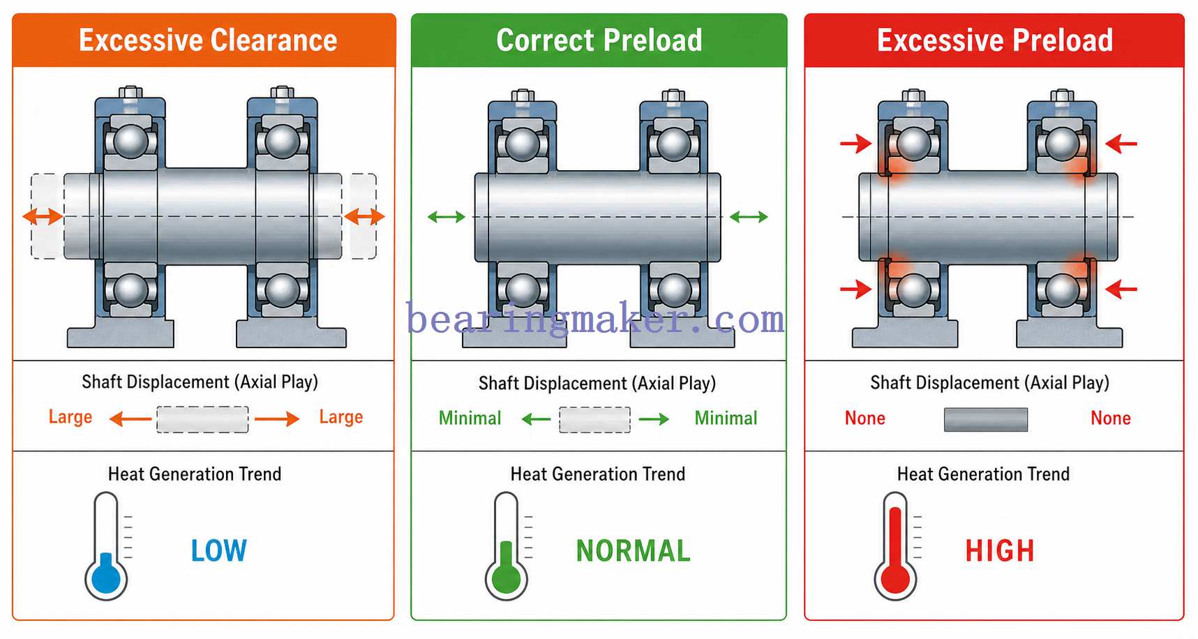
Why Preload Matters
Some thrust-bearing arrangements operate with deliberate preload.
Preload removes internal clearance by applying a controlled initial force before the external operating load is present.
It is common in:
- angular contact ball bearings
- tapered roller bearings
- precision spindle systems
Benefits of Preload
- increased axial stiffness
- reduced shaft movement
- improved rotational accuracy
- better rolling-element control
- reduced vibration in some systems
Risks of Excessive Preload
Too much preload increases:
- friction
- heat
- lubricant stress
- contact stress
and can greatly shorten bearing life.
Bearing Location: Fixed and Floating Arrangements
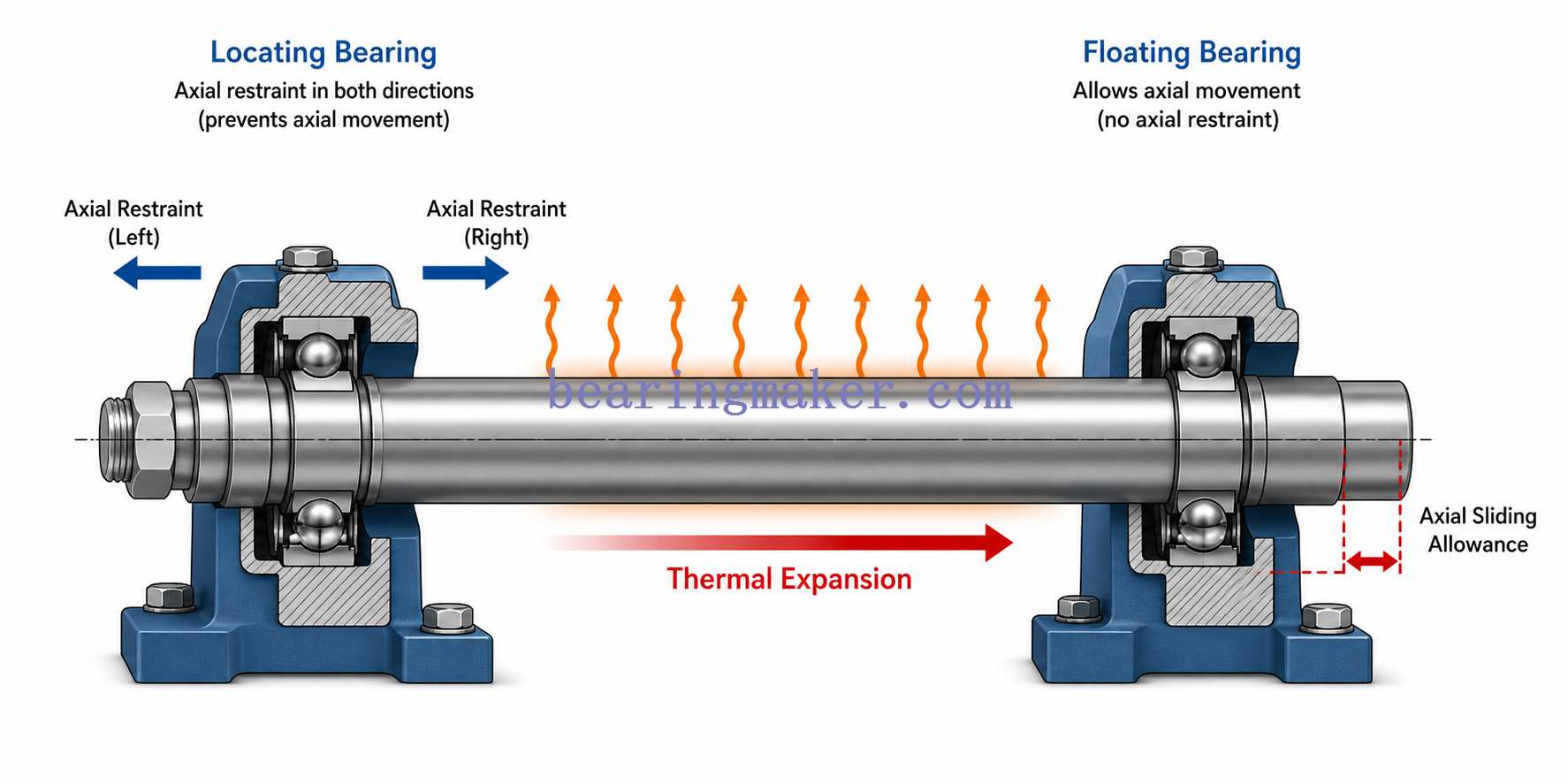
Thrust-bearing design cannot be separated from the entire shaft support system.
Many machines use:
- one locating bearing position
- one non-locating or floating bearing position
The locating position controls axial shaft movement.
The floating position allows thermal expansion of the shaft without creating excessive internal bearing force.
If both ends of a long shaft are rigidly fixed without accounting for thermal growth, operating temperature may create substantial unwanted axial preload.
This is an important consideration in:
- motors
- gearboxes
- long shafts
- high-temperature machinery
Installation Requirements
Correct bearing selection can still fail if installation is poor.
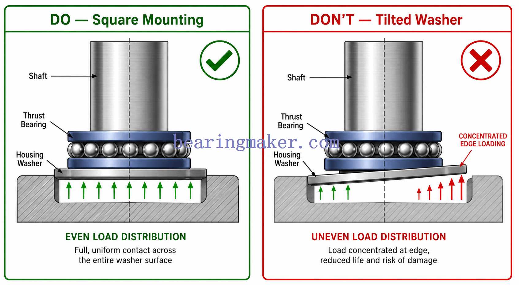
1. Keep Raceway Support Surfaces Square
Dedicated thrust bearings require accurately manufactured support surfaces.
Errors in:
- shaft shoulder squareness
- housing-face flatness
- washer seating
can cause uneven loading around the circumference.
2. Identify the Correct Washer
On many separable thrust bearings, shaft and housing washers are not interchangeable.
The shaft washer is designed to fit the shaft.
The housing washer is designed to locate against the stationary structure.
Incorrect assembly can produce:
- wrong fit
- poor centering
- abnormal loading
3. Never Transmit Installation Force Through Rolling Elements
When a bearing ring requires an interference fit, mounting force should be applied to that ring.
Installation force should not normally pass through:
- balls
- rollers
- opposite raceways
because this can damage rolling surfaces.
4. Keep Components Clean
Even small particles can damage precision raceways.
During assembly:
- clean shafts and housings
- use clean tools
- keep bearings covered until needed
- avoid introducing lint or metal chips
5. Verify Alignment
After assembly, verify that:
- shaft is square
- housing faces are aligned
- washers seat correctly
- bearing rotates smoothly
Common Thrust Bearing Failure Modes
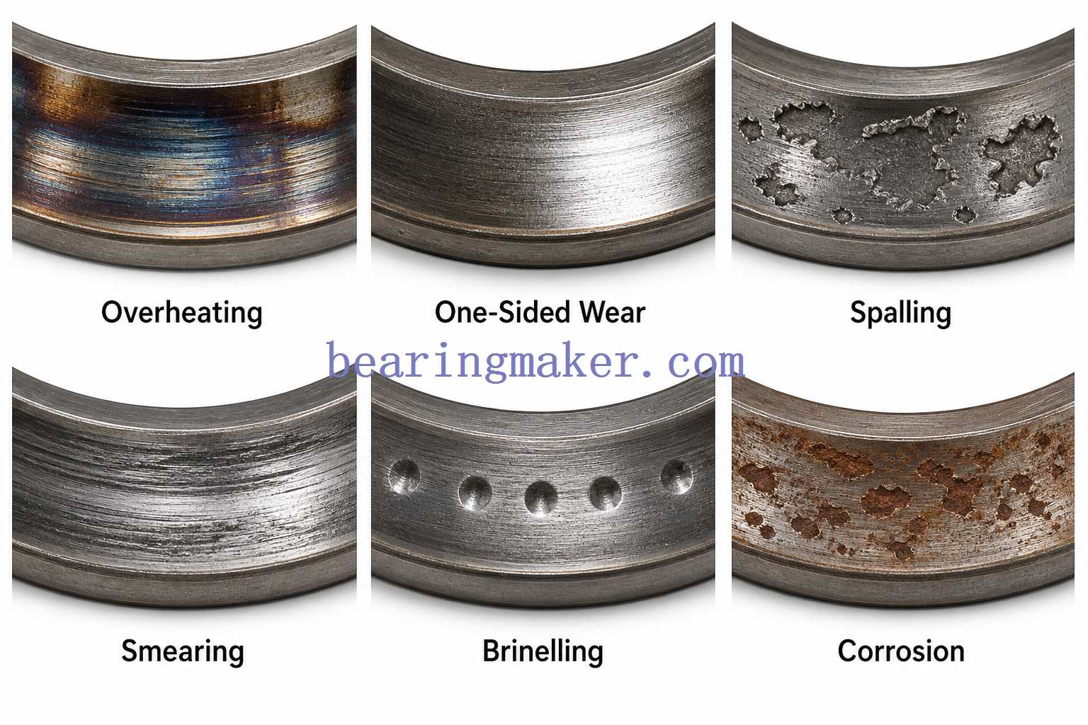
Understanding failure patterns helps distinguish bearing problems from lubrication, mounting, or machine-design problems.
1. Overheating
Possible causes include:
- excessive preload
- excessive lubricant
- incorrect lubricant viscosity
- excessive speed
- overload
- misalignment
What to Check
Compare operating temperature with the established baseline rather than relying on one universal temperature threshold.
2. One-Sided Raceway Wear
Likely causes:
- housing face not square
- shaft misalignment
- structural deflection
- washer not fully seated
This pattern indicates that load is not distributed uniformly.
3. Raceway Spalling
Spalling appears as flaking or material loss from a raceway.
Possible causes include:
- rolling-contact fatigue
- excessive load
- contamination
- poor lubrication
- surface damage
4. Smearing or Scuffing
These surface marks can develop when sliding becomes excessive.
Possible causes include:
- insufficient lubricant film
- unsuitable lubricant
- rapid acceleration
- low load combined with high speed
- roller skidding
5. Brinelling
Brinelling consists of permanent indentations in raceways.
Possible causes include:
- excessive static load
- impact during installation
- shock loading
6. Corrosion
Possible causes:
- water ingress
- condensation
- aggressive chemicals
- poor storage
Even minor corrosion damage can create stress concentrations that later develop into rolling-contact fatigue.
7. Cage Damage
Possible causes include:
- excessive speed
- insufficient lubrication
- misalignment
- roller skidding
- vibration
- shock loading
Maintenance and Condition Monitoring
A good maintenance program focuses on trends rather than waiting for visible failure.
Monitor Temperature
A stable machine often develops a repeatable temperature range.
An unexplained upward trend may indicate:
- lubrication deterioration
- increasing preload
- contamination
- increased load
- bearing damage
Monitor Vibration
Vibration analysis can identify developing rolling-element problems.
Useful indicators may include:
- overall vibration increase
- high-frequency vibration
- characteristic bearing defect frequencies
- changes in spectral patterns
Interpretation should account for:
- shaft speed
- bearing geometry
- machine structure
- operating load
Inspect Lubricant
Lubricant can provide information about bearing condition.
Look for:
- discoloration
- oxidation
- metallic debris
- water contamination
- unusual odor
- consistency changes
Check Axial Shaft Movement
Increasing axial play can indicate:
- bearing wear
- incorrect adjustment
- loosening
- structural movement
In precision applications, axial displacement may become unacceptable long before complete bearing failure.
Thrust Bearing Selection Checklist
Before specifying a thrust bearing, collect the following information:
| Parameter | Information Needed |
|---|---|
| Shaft diameter | mm or in |
| Axial load | Normal and peak |
| Load direction | One-way or reversing |
| Radial load | Magnitude if present |
| Rotational speed | rpm |
| Required life | Hours or revolutions |
| Duty cycle | Continuous/intermittent |
| Shock loading | Yes/no and magnitude |
| Required stiffness | Normal/high/precision |
| Misalignment | Expected angular error |
| Available axial space | mm |
| Available radial space | mm |
| Temperature | Minimum/normal/maximum |
| Contamination | Dust/water/chemicals |
| Lubrication | Grease/oil/other |
| Bearing location | Locating/floating |
| Precision | Standard or high accuracy |
| Maintenance access | Easy/limited |
| Corrosion requirement | Standard or enhanced |
This information usually narrows the appropriate bearing family much more effectively than choosing by dimensions alone.
Frequently Asked Questions
What Is a Thrust Bearing?
A thrust bearing is a bearing designed primarily to support forces acting parallel to a shaft’s rotational axis.
It prevents excessive axial displacement while allowing rotation.
What Is the Difference Between a Thrust Bearing and a Radial Bearing?
A radial bearing primarily supports load perpendicular to the shaft.
A thrust bearing primarily supports load parallel to the shaft.
Some bearings, including angular contact ball bearings and tapered roller bearings, are designed to support both simultaneously.
Can a Thrust Bearing Handle Radial Load?
Many conventional thrust ball, cylindrical roller thrust, and needle roller thrust bearings should not carry significant radial load.
Other designs, such as:
- angular contact ball bearings
- tapered roller bearings
- some spherical roller thrust bearings
can support combined loads.
The allowable radial-to-axial relationship must be checked for the specific bearing design.
Which Thrust Bearing Can Carry the Highest Load?
There is no universal answer because load capacity depends heavily on bearing size.
As a general design tendency:
- thrust ball bearings favor speed
- roller thrust bearings favor higher load
- spherical roller thrust bearings are especially suitable for very heavy axial load with misalignment
- tapered roller bearings are excellent for heavy combined radial and axial loads
Which Thrust Bearing Is Best for High Speed?
Ball-based designs are generally preferred for high-speed service because they produce less friction than roller designs.
Potential choices include:
- thrust ball bearings for predominantly axial load
- angular contact ball bearings for combined loads and high precision
Lubrication, bearing size, preload, and cooling still determine the actual usable speed.
Which Thrust Bearing Uses the Least Space?
Needle roller thrust bearings are particularly useful when axial space is extremely limited.
They can provide high axial load capacity in a very thin assembly.
What Is the Difference Between a Thrust Ball Bearing and an Angular Contact Bearing?
A conventional thrust ball bearing is designed primarily for axial load and generally cannot support significant radial load.
An angular contact bearing uses inclined raceways and can support simultaneous:
- axial load
- radial load
Angular contact bearings are also widely used where high speed, rigidity, and precise shaft positioning are required.
Can a Thrust Bearing Support Load in Both Directions?
Yes, but only if the bearing or bearing arrangement is designed for it.
Options include:
- double-direction thrust ball bearings
- opposed angular contact bearings
- opposed tapered roller bearings
A single-direction thrust bearing supports thrust from only one direction.
What Causes a Thrust Bearing to Overheat?
Common causes include:
- excessive preload
- excessive or unsuitable lubricant
- excessive speed
- overload
- misalignment
- insufficient internal clearance
- damaged raceways
The cause should be diagnosed rather than assuming that more lubrication will solve the problem.
How Do I Know When a Thrust Bearing Should Be Replaced?
Possible warning signs include:
- increasing vibration
- persistent temperature increase
- unusual noise
- excessive axial play
- rough rotation
- metal particles in lubricant
- visible spalling or corrosion
- damaged cage
Condition trends are generally more useful than one isolated measurement.
Do Thrust Bearings Need Lubrication?
Most rolling-element thrust bearings require lubrication.
Depending on operating conditions, they may use:
- grease
- oil
- specialized lubrication systems
Lubrication reduces friction and wear while also helping protect surfaces from corrosion and contamination.
Conclusion
Thrust bearings all perform the same basic task—controlling axial force—but the way they accomplish it varies considerably.
The main choices can be summarized simply:
- Thrust ball bearings — good for relatively high speed and moderate pure axial loads.
- Angular contact ball bearings — suitable for high-speed combined radial and axial loads.
- Needle roller thrust bearings — ideal where axial space is extremely limited.
- Cylindrical roller thrust bearings — provide high axial capacity and rigidity.
- Spherical roller thrust bearings — excel under very heavy thrust loads where shaft deflection or misalignment is present.
- Tapered roller bearings — well suited to heavy combined radial and axial loads.
But choosing the correct bearing requires more than identifying the load direction.
A complete selection should consider:
load magnitude → load direction → speed → required life → static load → rigidity → misalignment → available space → lubrication → temperature → environment → mounting → preload and clearance.
The thrust bearing should also be considered as part of the complete shaft-support system, not as an isolated component.
A correctly selected bearing paired with accurate mounting, suitable lubrication, proper axial location, and regular condition monitoring can provide predictable service life. The wrong bearing—or the right bearing installed incorrectly—can cause excessive heat, wear, vibration, and damage far beyond the bearing itself.
