
Thin section bearings are designed for applications where engineers need a large bore, low weight, and compact radial envelope without giving up smooth rotary motion.
They are widely used in robotics, optical systems, medical equipment, semiconductor machinery, aerospace mechanisms, rotary tables, positioning systems, and other machines where conventional bearings consume too much space or add unnecessary mass.
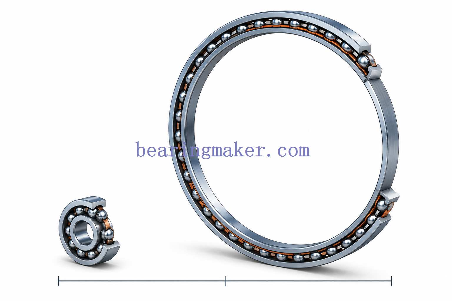
Their advantage is easy to understand: a thin section bearing can support a relatively large rotating diameter while occupying much less radial space than a conventional bearing of similar bore size.
The engineering challenge is equally important.
Because the rings are thinner, thin section bearings are generally more sensitive to:
- housing distortion
- shaft roundness
- mounting accuracy
- preload
- interference fits
- moment loads
- structural deflection
As a result, selecting a thin section bearing is not simply a matter of matching bore diameter and load rating.
This guide explains how thin section bearings work, the main types available, how they differ from standard ball bearings and crossed roller bearings, and what designers should consider when selecting, mounting, and maintaining them.
What Is a Thin Section Bearing?
A thin section bearing is a rolling bearing with a relatively small cross-sectional height compared with its bore diameter.
Its defining advantage is that the bearing can maintain a large internal opening while occupying relatively little radial space.
This makes it particularly useful where a machine requires:
- a large hollow shaft
- internal cable routing
- optical or fluid passage
- low rotating mass
- compact joint geometry
- low system inertia
Thin section bearings are commonly based on ball-bearing geometry, although different raceway configurations may be used depending on the load direction.
Thin Section Does Not Mean Miniature
Thin section bearings and miniature bearings solve different design problems.
A miniature bearing is small in overall size.
A thin section bearing may actually have a relatively large diameter but still use a small cross-section.
For example, a robot joint may require a large central passage for:
- electrical cables
- pneumatic lines
- sensors
- drive components
A conventional bearing with the same bore may have a much larger outside diameter and cross-section.
A thin section bearing allows the designer to preserve that central opening while keeping the joint compact.
| Feature | Thin Section Bearing | Miniature Bearing |
|---|---|---|
| Primary goal | Large bore with small cross-section | Small overall dimensions |
| Typical diameter | Can be relatively large | Small |
| Main packaging advantage | Reduced radial envelope | Reduced total size |
| Common applications | Robotics, optics, rotary joints | Instruments, small motors |
| Structural challenge | Ring deformation | Small-scale manufacturing accuracy |
Why Use Thin Section Bearings?
Thin section bearings are usually selected because of system-level packaging requirements, not simply because they look smaller.
Their benefits become more apparent when considered as part of the overall machine.
Reduced Radial Space
A conventional bearing generally becomes larger in cross-section as bore diameter increases.
Thin section designs reduce this growth.
This allows designers to reduce:
- housing diameter
- joint thickness
- rotating assembly size
- surrounding structural material
Large Hollow Bore
A large center opening is valuable when the bearing must surround:
- cables
- hoses
- optical paths
- drive shafts
- sensors
- vacuum lines
- internal mechanisms
This is one reason thin section bearings are common in robotic joints and precision rotary equipment.
Lower Weight
Reducing ring cross-section can significantly decrease bearing mass.
Lower bearing weight can improve:
- robotic payload efficiency
- aerospace weight budgets
- moving-system acceleration
- energy consumption
Lower Rotational Inertia
A lighter rotating assembly generally requires less torque to accelerate and decelerate.
This can be important in:
- robotic axes
- indexing systems
- scanning equipment
- optical positioning systems
where rapid direction changes are common.
Compact System Architecture
A smaller bearing cross-section can allow the complete machine to become smaller.
The benefit may extend beyond the bearing itself.
A thinner bearing can enable:
- smaller housings
- shorter fasteners
- reduced structural mass
- more room for motors or gearing
- easier internal routing
The Main Trade-Off: Thin Rings Are Less Rigid
The advantages of thin section bearings come with an important design consequence.
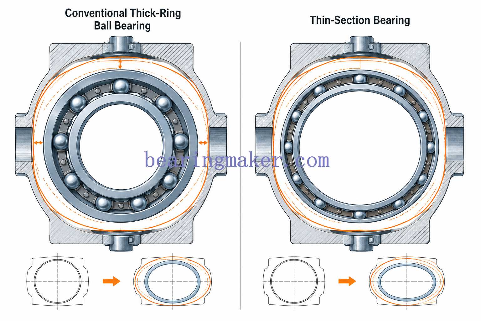
Their rings are generally less structurally rigid than the thicker rings of conventional bearings.
This means the installed bearing is more influenced by the surrounding machine structure.
A thin outer ring may follow the shape of an imperfect housing.
A thin inner ring may conform more closely to:
- shaft ovality
- interference fit
- local clamping forces
This can change the geometry of the raceways even when the bearing itself was manufactured accurately.
Possible results include:
- uneven load distribution
- higher running torque
- reduced internal clearance
- unexpected preload
- vibration
- reduced fatigue life
For this reason, the performance of a thin section bearing depends heavily on the bearing + shaft + housing system.
How Thin Section Bearings Work
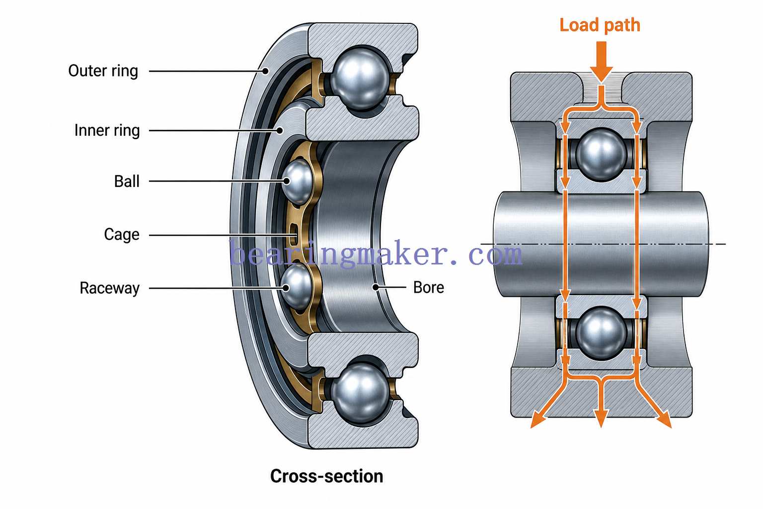
Most thin section bearings use balls rolling between inner- and outer-ring raceways.
The basic load path is:
shaft → inner ring → rolling elements → outer ring → housing
The type and direction of load that the bearing can support depend primarily on the raceway geometry and contact angle.
Important internal components typically include:
- inner ring
- outer ring
- balls
- cage or separator
- raceways
- lubricant
- optional seals or shields
Even though the bearing section is small, the same basic rolling-contact principles used in conventional ball bearings still apply.
However, the reduced ring thickness makes structural support more important.
Main Types of Thin Section Bearings
Thin section ball bearings are commonly classified according to contact geometry.
The three most important forms are:
- radial contact
- angular contact
- four-point contact
Each is optimized for a different load condition.
1. Radial Contact Thin Section Bearings
Radial contact thin section bearings are designed primarily for radial loading.
Their raceway geometry resembles that of a conventional deep groove or radial ball bearing.
They are often selected when:
- radial load dominates
- speed is relatively high
- friction must remain low
- axial load is limited
Advantages
- low rolling resistance
- good speed capability
- smooth rotation
- simple arrangement
- suitable for general radial support
Limitations
- axial capacity is limited compared with angular-contact designs
- moment-load capability may be limited
- poor housing geometry can distort raceway contact
Typical Applications
- precision instruments
- lightweight rotary mechanisms
- optical assemblies
- general automation equipment
- compact rotating equipment
2. Angular Contact Thin Section Bearings
Angular contact thin section bearings have raceways arranged so that the load is transmitted at an angle relative to the radial plane.
This allows them to carry:
- radial load
- significant axial load in one direction
The contact angle strongly influences how the bearing distributes forces.
In general:
- smaller contact angle favors speed and radial-load capability
- larger contact angle increases axial-load capability
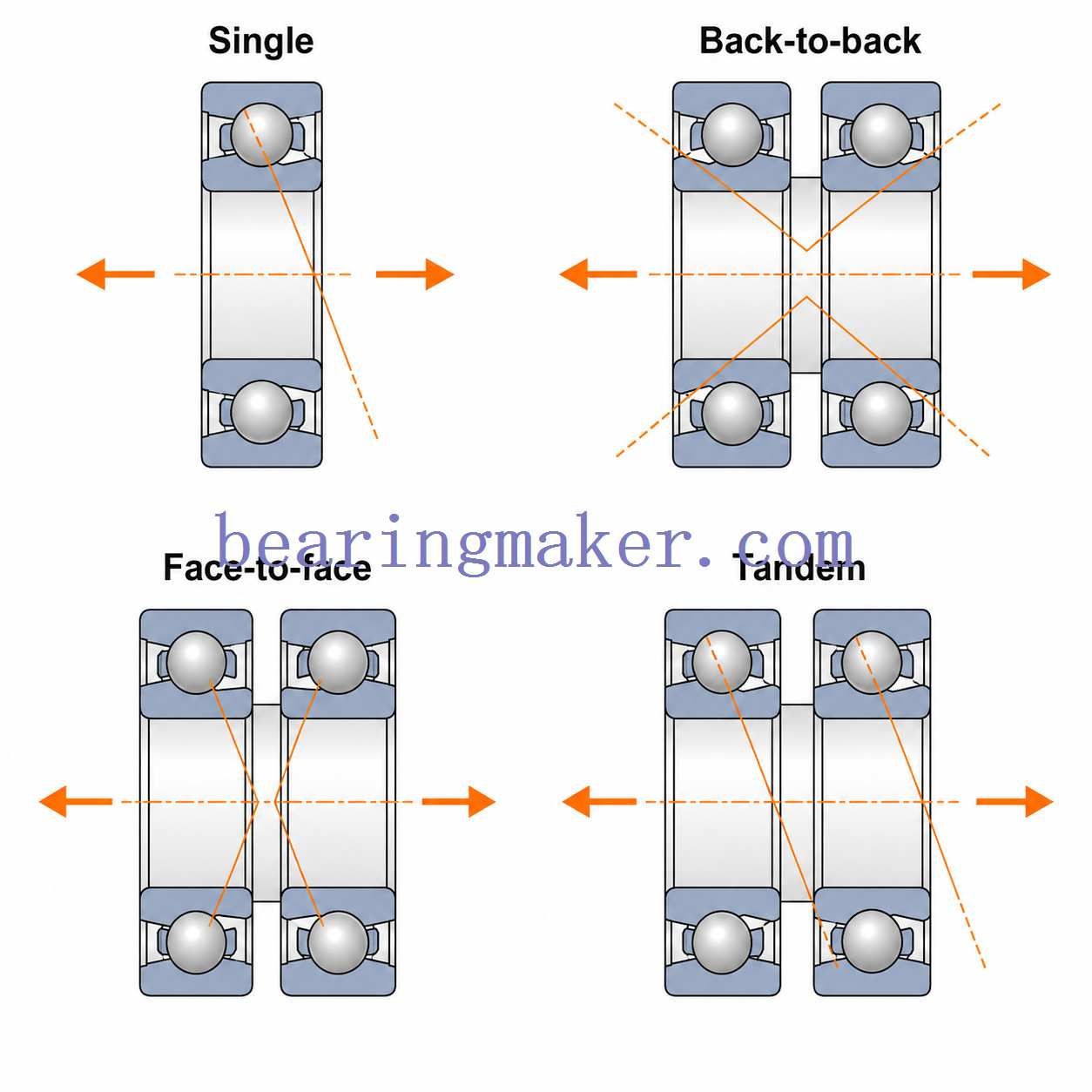
Paired Angular Contact Arrangements
A single angular contact bearing normally carries significant axial force primarily in one direction.
For bidirectional thrust or increased rigidity, two or more bearings may be arranged together.
Back-to-Back
Load lines diverge outward.
This arrangement generally provides:
- high moment stiffness
- good axial positioning
- wide effective support spacing
Face-to-Face
Load lines converge inward.
This arrangement may offer:
- different misalignment behavior
- shorter effective support spacing
Tandem
Both bearings face the same direction.
This increases axial-load capability in one direction.
A separate opposing bearing may still be required if load reverses.
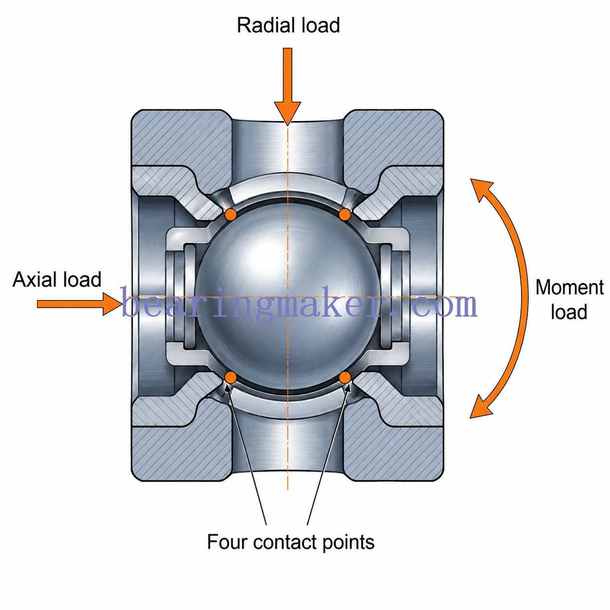
3. Four-Point Contact Thin Section Bearings
Four-point contact bearings are especially important in thin section applications because they can support several load directions within a single bearing.
Their raceways are shaped so that balls can theoretically contact the raceways at four locations depending on the applied load.
They can support combinations of:
- radial load
- axial load in either direction
- moment load
This allows one four-point contact bearing to replace some multi-bearing arrangements where space is limited.
Advantages
- compact axial arrangement
- bidirectional axial load capability
- combined-load capability
- moment-load capability
- reduced number of bearings in some systems
Limitations
Four-point contact bearings should not automatically be treated as the best choice for every combined-load application.
Potential limitations include:
- higher friction than a pure radial-contact bearing
- sensitivity to preload and mounting distortion
- less favorable radial-load performance in some conditions
- lower rigidity than some paired angular contact or crossed roller arrangements
In precision systems, the required rigidity and allowable deflection may determine whether a four-point contact bearing is sufficient.
Radial Contact vs. Angular Contact vs. Four-Point Contact
| Feature | Radial Contact | Angular Contact | Four-Point Contact |
|---|---|---|---|
| Radial load | Good | Good | Moderate–Good |
| Axial load | Limited | High in one direction | Both directions |
| Moment load | Limited | High when paired | Good |
| Speed | High | High | Moderate–High |
| Friction | Low | Low–Moderate | Moderate |
| Rigidity | Moderate | High when paired | Moderate–High |
| Arrangement | Usually single | Often paired | Often single |
| Best use | Predominantly radial loads | Precision combined loads | Compact multi-direction loads |
These are general tendencies. Actual performance depends on bearing geometry, size, preload, fit, and surrounding structure.
Constant-Section Thin Section Bearings
One distinctive thin section design concept is the constant cross-section.
In some bearing series, the cross-sectional dimensions remain nearly unchanged as bore diameter increases.
This differs from many conventional bearing series, where larger bore diameters are normally accompanied by larger bearing cross-sections.
The advantage is predictable packaging.
A designer can increase:
- bore size
- central opening
- rotary diameter
without proportionally increasing the radial thickness of the bearing.
This is particularly useful when machine architecture is built around a fixed radial envelope.
However, not every bearing marketed as “thin section” follows exactly the same constant-section geometry, so dimensions should always be verified for the specific design.

Thin Section Bearings vs. Standard Ball Bearings
Thin section bearings and conventional ball bearings use similar rolling-element principles, but their structural behavior can be very different.
| Feature | Thin Section Bearing | Standard Ball Bearing |
|---|---|---|
| Radial envelope | Small | Larger |
| Bore-to-section ratio | High | Lower |
| Weight | Lower | Higher |
| Ring stiffness | Lower | Higher |
| Load capacity for similar bore | Generally lower | Generally higher |
| Housing sensitivity | Higher | Lower |
| Large hollow bore | Excellent | Less packaging-efficient |
| Installation sensitivity | Higher | Lower |
| Typical applications | Robotics, optics, medical systems | Motors, pumps, general machinery |
When a Standard Bearing Is Better
A thin section bearing is not automatically the better design.
A conventional bearing may be preferable when:
- radial space is not limited
- load capacity is the dominant requirement
- housing stiffness is poor
- installation accuracy is difficult to control
- lower cost is important
Thin section bearings provide the most value when the machine genuinely benefits from their compact cross-section.
Thin Section Bearings vs. Crossed Roller Bearings
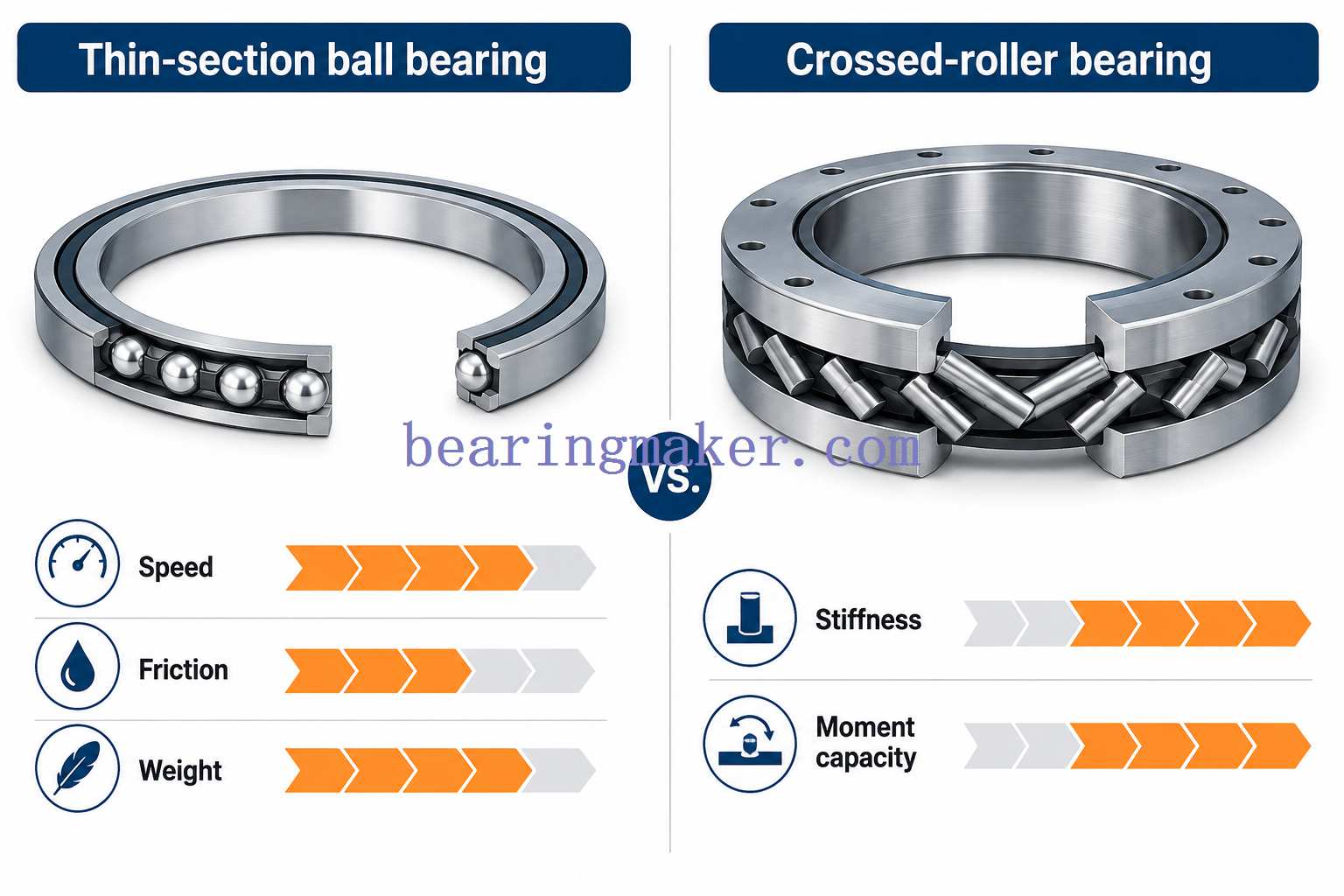
Another common engineering decision is whether to use a thin section ball bearing or a crossed roller bearing.
Both can support large-diameter rotary structures, but their behavior differs considerably.
Thin Section Ball Bearings
Typical strengths include:
- low friction
- higher speed capability
- lower mass
- smooth motion
- relatively simple lubrication
They are often attractive where:
- low inertia
- speed
- low torque
matter more than maximum rigidity.
Crossed Roller Bearings
Crossed roller bearings arrange cylindrical rollers alternately at approximately 90 degrees.
This gives them excellent capability for:
- radial load
- axial load
- overturning moment
They generally provide:
- high rigidity
- high moment stiffness
- small elastic displacement
Which One Should You Choose?
A simplified comparison:
| Requirement | Thin Section Ball | Crossed Roller |
|---|---|---|
| Low friction | Excellent | Good |
| High speed | Better | Lower |
| Low weight | Better | Heavier |
| High rigidity | Moderate | Excellent |
| Moment capacity | Moderate–High depending on arrangement | Very high |
| Low inertia | Better | Lower |
| Precision positioning | Good–Excellent | Excellent |
| Compact cross-section | Excellent | Excellent |
If the machine requires low weight and fast rotation, a thin section ball bearing may be preferable.
If very high stiffness and moment resistance dominate the design, a crossed roller bearing may be the stronger candidate.
Understanding Loads on Thin Section Bearings
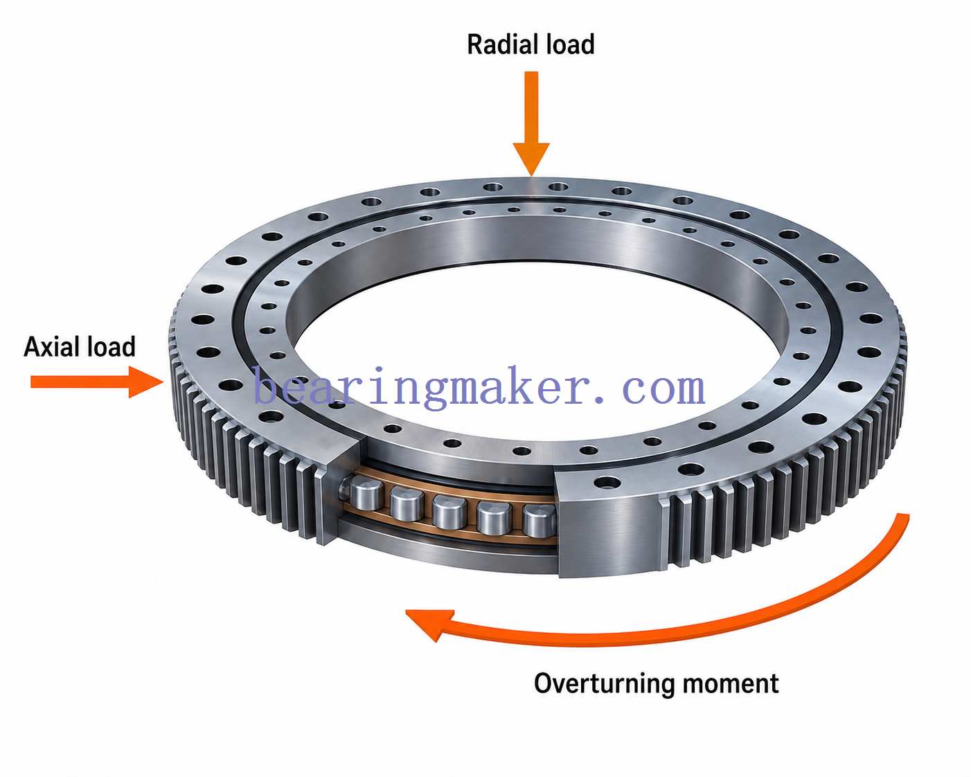
Bearing selection should always begin with the actual loads acting on the rotating assembly.
Radial Load
A radial load acts perpendicular to the axis of rotation.
Examples include:
- component weight
- belt tension
- gear forces
- external side loads
Axial Load
An axial load acts parallel to the axis of rotation.
Examples include:
- thrust from helical gears
- actuator force
- vertical component weight
- axial clamping loads
Moment Load
A moment attempts to tilt the rotating structure relative to the bearing.
Moment loads are common in:
- robotic arms
- gimbals
- rotary tables
- large optical assemblies
Because thin section bearings are often used in large-diameter structures, moment loading can become a major design consideration even when radial and axial forces appear moderate.
Selecting the Contact Type by Load
| Load Condition | Common Starting Point |
|---|---|
| Mainly radial | Radial contact |
| Radial + axial in one direction | Angular contact |
| Axial load in both directions | Four-point contact or opposed angular contact |
| High moment load | Paired angular contact or four-point contact |
| High precision + high rigidity | Preloaded angular contact pair |
| Very high rigidity and moment capacity | Consider crossed roller design |
This table is an initial screening tool rather than a replacement for load calculations.
Load Capacity and Bearing Life
Thin section ball bearings are subject to the same basic rolling-contact fatigue principles as other ball bearings.
A simplified basic rating-life relationship is:
L10=(CP)3L_{10} = \left(\frac{C}{P}\right)^3
where:
- L10L_{10} = basic rating life in millions of revolutions
- CC = basic dynamic load rating
- PP = equivalent dynamic bearing load
To express life in operating hours:
L10h=10660n(CP)3L_{10h} = \frac{10^6}{60n} \left(\frac{C}{P}\right)^3
where:
- nn = rotational speed in rpm
Why Load Has Such a Large Effect
Because load is raised to the third power in the basic ball-bearing life equation, relatively small changes in equivalent load can cause large changes in calculated fatigue life.
If load is reduced by half while all other conditions remain unchanged:
(2)3=8(2)^3 = 8
The theoretical basic rating life increases by a factor of eight.
Why Thin Section Bearing Life Requires Extra Caution
Catalog fatigue calculations assume a reasonably correct internal load distribution.
Thin section bearings can deviate from that assumption if the supporting structure distorts the rings.
Possible causes include:
- non-round housing bore
- insufficient housing wall thickness
- uneven bolt tightening
- shaft ovality
- excessive interference
- structural deflection
These effects may concentrate load on only part of the raceway.
As a result, a bearing with an apparently adequate catalog life may still experience reduced real-world service life if the mounting structure is poor.
Static Load Capacity
Dynamic fatigue life is not the only load limit.
The basic static load rating becomes important when the bearing experiences:
- high stationary loads
- shock
- impact
- very slow rotation
Excessive static loading can create permanent deformation at the ball-to-raceway contacts.
This may later produce:
- vibration
- noise
- reduced accuracy
- premature fatigue
For precision systems, allowable static deformation may need to be much lower than the theoretical damage threshold.
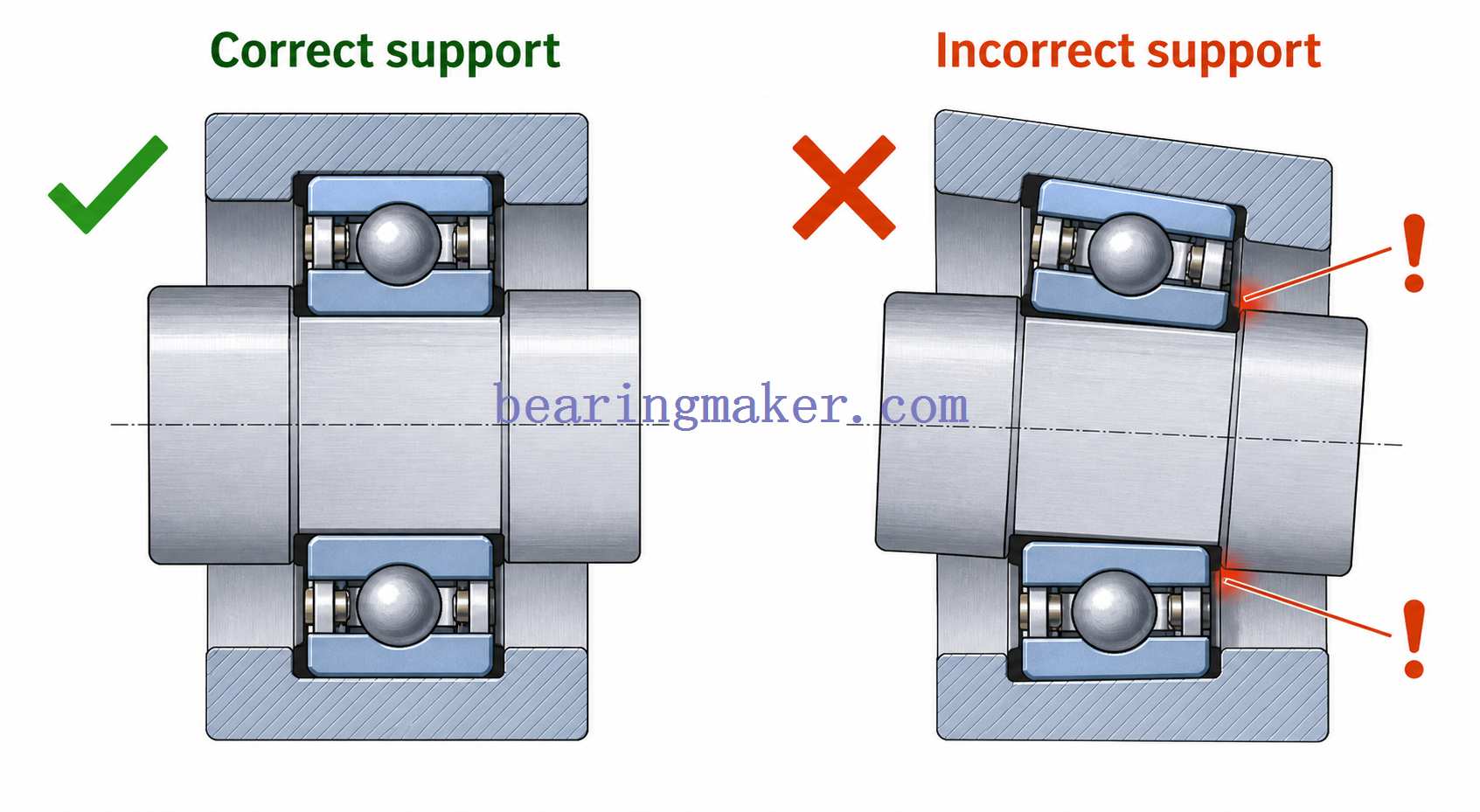
Housing Stiffness: One of the Most Important Design Factors
Housing stiffness deserves special attention in thin section bearing applications.
Because the outer ring is thin, it can conform to the shape of the housing bore.
If the housing becomes oval, the bearing may also become oval.
Potential consequences include:
- altered internal clearance
- uneven ball loading
- higher torque
- premature fatigue
- reduced rotational accuracy
This is especially important with lightweight housings made from:
- aluminum
- thin-walled structures
- split housings
- bolted assemblies
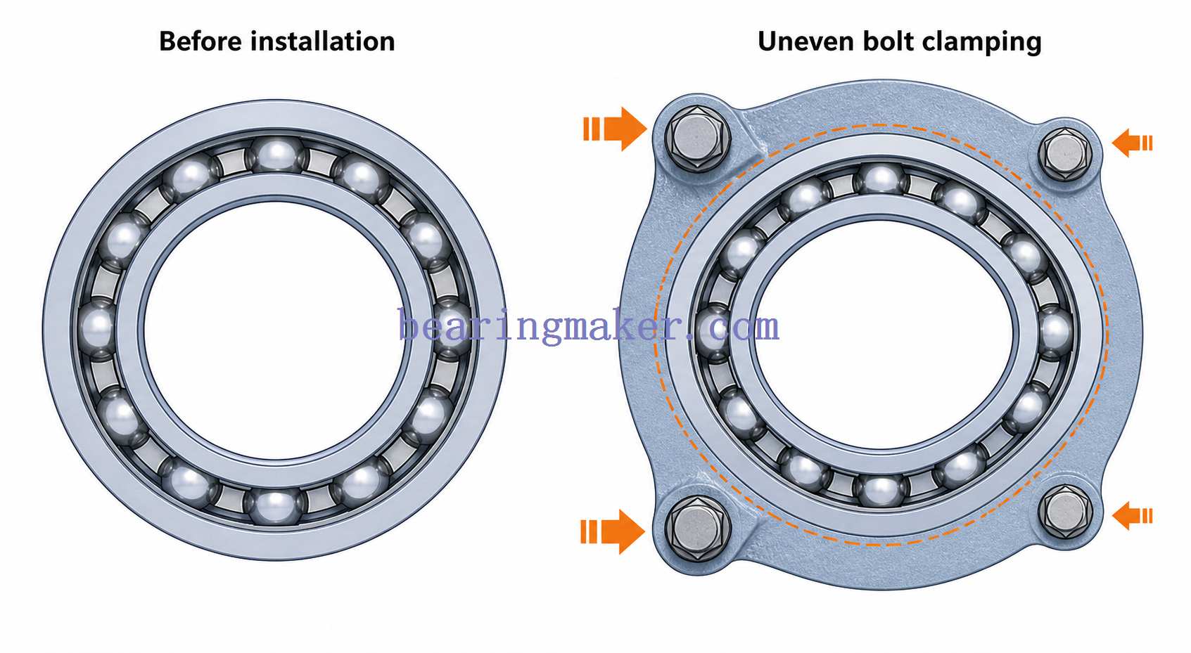
Bolt Pattern Distortion
Mounting bolts can deform a housing locally.
If bolts are:
- unevenly spaced
- over-tightened
- installed into a flexible flange
the housing bore may no longer remain round after assembly.
This can distort the bearing outer ring.
Shaft Stiffness and Roundness
The same principle applies to the inner ring.
A thin inner ring may conform more closely to an out-of-round or flexible shaft.
Important shaft characteristics include:
- diameter tolerance
- roundness
- cylindricity
- surface finish
- stiffness
- shoulder squareness
A precision bearing cannot compensate for a poorly manufactured shaft.
Fits and Mounting
Bearing fits must control the rings without creating excessive distortion.
This balance is especially important with thin section bearings.
Excessive Interference
Too much interference can:
- expand the inner ring
- compress the outer ring
- reduce internal clearance
- create unintended preload
- increase running torque
- increase heat
The assumption that “a tighter fit is safer” can therefore be harmful.
Excessively Loose Fits
Fits that are too loose can lead to:
- ring creep
- fretting
- wear
- reduced positioning accuracy
The appropriate fit depends on:
- load direction
- rotating or stationary load
- ring thickness
- temperature
- shaft and housing materials
Mounting Shoulders
Shoulders should provide:
- adequate support
- correct squareness
- sufficient contact area
A distorted shoulder can tilt the bearing and create localized loading.
Internal Clearance and Preload
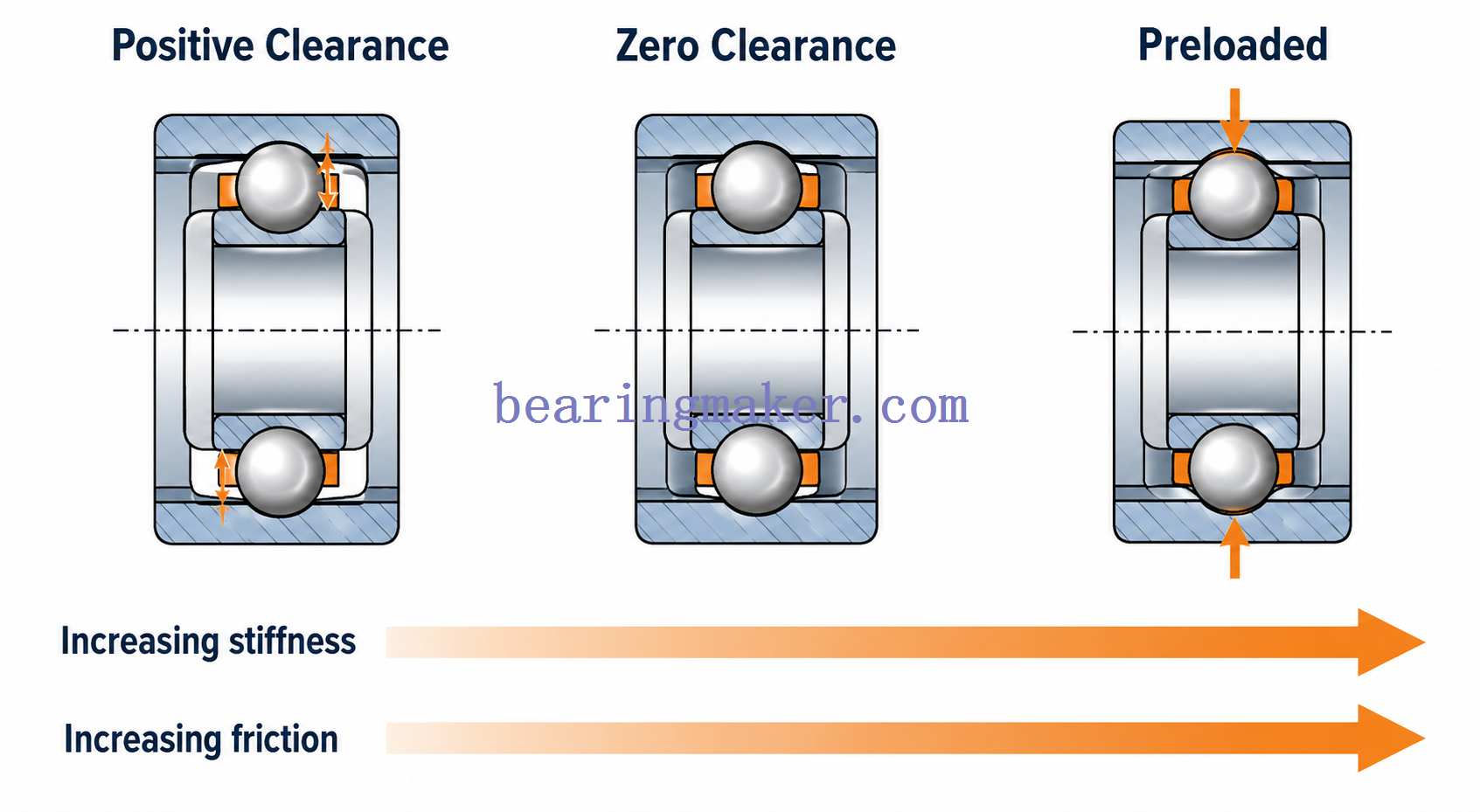
Internal clearance strongly affects bearing behavior.
Too Much Clearance
Excessive clearance can cause:
- shaft movement
- lower rigidity
- vibration
- reduced positional accuracy
Too Little Clearance
Insufficient clearance can cause:
- friction
- heat
- shortened lubricant life
- reduced fatigue life
Preload
Preload intentionally removes internal clearance by applying a controlled initial load.
It is commonly used in:
- paired angular contact bearings
- precision rotary equipment
- robotic joints
- optical systems
Potential benefits include:
- increased rigidity
- reduced free play
- improved rotational accuracy
- more consistent rolling-element contact
Excessive Preload
Too much preload can create:
- excessive running torque
- heat
- lubricant breakdown
- increased raceway stress
- shortened bearing life
Thin section bearings can be especially sensitive because mounting distortion may add unintended preload on top of the designed value.
Bearing Accuracy vs. System Accuracy
A high-precision bearing does not guarantee a high-precision machine.
Total system accuracy depends on:
- bearing runout
- shaft runout
- housing accuracy
- mounting-face squareness
- preload
- structural deformation
- temperature
This distinction is especially important in:
- optical equipment
- robotics
- scanning equipment
- metrology systems
Radial Runout
Radial runout describes variation perpendicular to the rotational axis.
It can cause:
- tool or sensor displacement
- vibration
- positioning error
Axial Runout
Axial runout describes variation parallel to the rotational axis.
It is particularly important in:
- rotary tables
- optical assemblies
- precision turntables
Speed Considerations
Thin section bearings can operate at high rotational speeds, but RPM alone does not describe bearing speed conditions accurately.
A large bearing rotating at a moderate RPM can still generate high rolling-element velocity.
For example:
- a 30 mm bearing at 1,000 rpm
- a 300 mm bearing at 1,000 rpm
operate at the same shaft RPM but not at the same rolling-element surface speed.
Mean Diameter and Speed
Bearing speed evaluation often considers both:
- rotational speed
- mean bearing diameter
This is why large-diameter thin section bearings may require careful lubrication and heat analysis even at apparently modest RPM.
High-Speed Challenges
At increasing speed:
- centrifugal forces increase
- cage forces increase
- lubricant churning increases
- heat generation rises
Bearing selection must therefore consider:
- cage design
- lubrication
- preload
- bearing diameter
- cooling
Thin Section Bearing Materials
Material selection depends on:
- load
- corrosion
- temperature
- speed
- electrical requirements
- weight
Bearing Steel
Hardened bearing steel is commonly used because it provides:
- high hardness
- excellent rolling-contact fatigue resistance
- good dimensional stability
- high wear resistance
It is suitable for many general-purpose precision applications.
Stainless Steel
Stainless steel may be selected where corrosion resistance is required.
Common environments include:
- medical equipment
- washdown systems
- humid conditions
- food-related machinery
- outdoor equipment
Different stainless grades have different:
- hardness
- corrosion resistance
- load capability
The correct grade should therefore be selected according to the actual operating environment.
Hybrid Ceramic Bearings
Hybrid bearings combine:
- ceramic balls
- metallic rings
Potential advantages include:
- lower ball density
- electrical insulation
- high hardness
- reduced centrifugal loading
They may be useful in selected:
- high-speed
- electrically sensitive
- precision applications
They are not automatically superior for every thin section application.
Open, Shielded, and Sealed Thin Section Bearings
The closure design affects friction and contamination protection.
Open Bearings
Advantages:
- lowest seal-related friction
- easier lubricant circulation
- high potential speed
Limitations:
- limited contamination protection
Shielded Bearings
Metal shields provide moderate protection while maintaining relatively low friction.
They are useful where:
- dust protection is needed
- high speed remains important
Sealed Bearings
Contact or low-contact seals provide stronger protection against:
- dust
- moisture
- debris
The trade-off may include:
- higher friction
- greater heat generation
- lower limiting speed
| Configuration | Friction | Protection | Speed Potential |
|---|---|---|---|
| Open | Lowest | Low | Highest |
| Shielded | Low | Moderate | High |
| Sealed | Higher | High | Moderate–High |
Lubrication
Lubrication is critical to both performance and bearing life.
Thin section bearings commonly use:
- grease
- oil
- specialized low-torque lubricants
Grease
Grease is common because it provides:
- simple retention
- good contamination protection
- low maintenance
It is often preferred in:
- robotics
- instrumentation
- general precision equipment
Oil
Oil may be used where:
- speed is high
- heat removal is important
- the machine already uses circulating oil
Overlubrication
More lubricant is not always better.
Excessive grease can cause:
- churning
- drag
- increased running torque
- elevated temperature
This can be especially noticeable in low-torque precision systems.
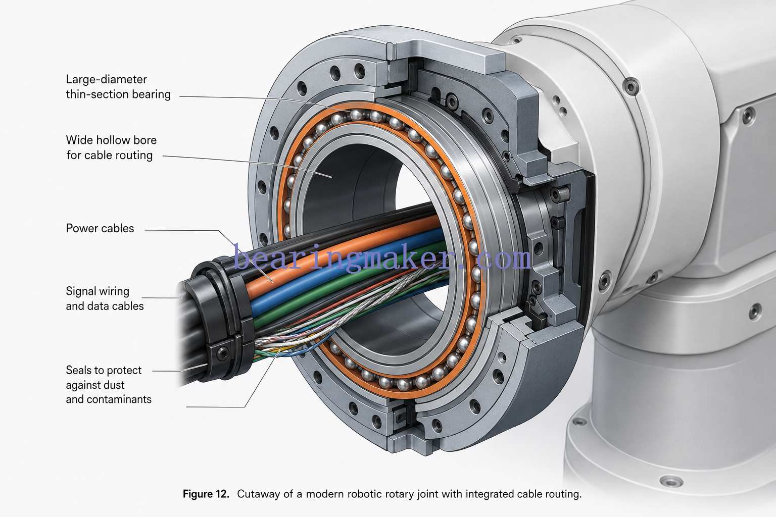
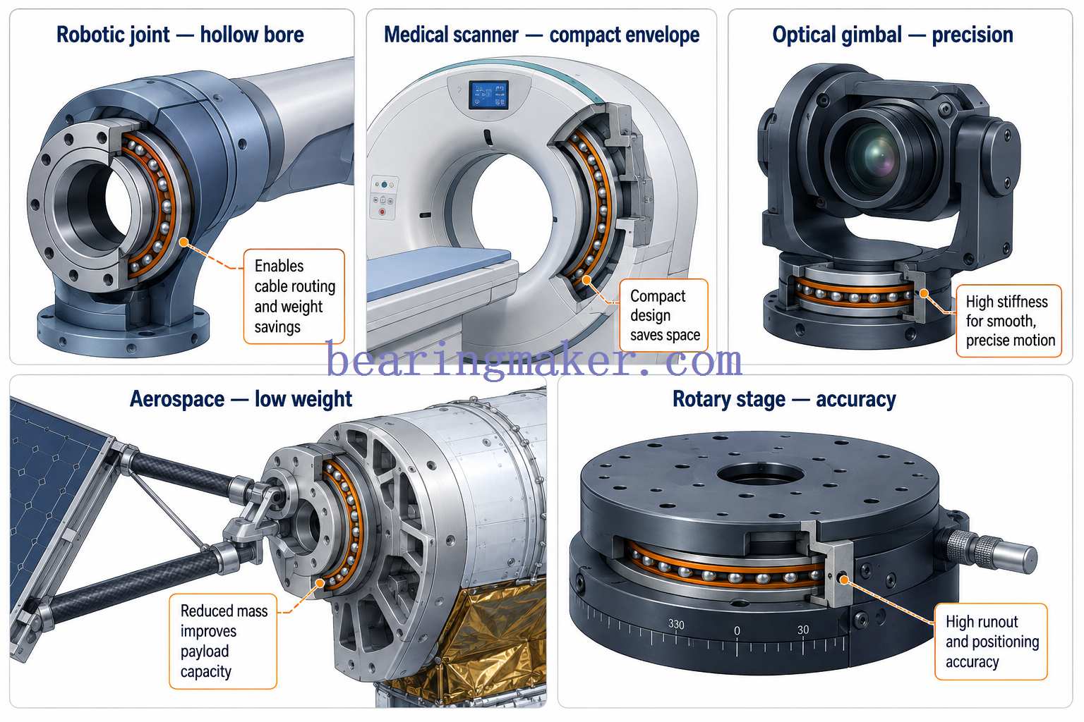
Thin Section Bearings in Robotics
Robotics is one of the most natural applications for thin section bearings.
A robot joint often requires:
- large central opening
- compact outer diameter
- low weight
- low inertia
- good precision
- combined-load capability
The hollow bore may be used to route:
- power cables
- data cables
- pneumatic lines
- sensors
This reduces the need to route components externally around the joint.
Key Design Considerations for Robot Joints
Important factors include:
- moment load from arm reach
- joint stiffness
- bearing preload
- gearbox forces
- housing deformation
- repeated reversing motion
In many robotic joints, stiffness can be more important than nominal bearing fatigue life.
Medical Equipment
Thin section bearings are used in medical equipment where compact size and smooth rotation are important.
Applications may include:
- imaging equipment
- scanning systems
- positioning mechanisms
- robotic medical equipment
- laboratory instruments
Important considerations include:
- low noise
- precision
- corrosion resistance
- lubricant compatibility
- cleanliness
Optical and Imaging Systems
Optical systems often require a large central opening for:
- lenses
- cameras
- laser paths
- sensors
A thin section bearing can provide rotary support without obstructing the optical path.
Key requirements may include:
- low runout
- smooth torque
- low vibration
- low particulate generation
Aerospace Mechanisms
Aerospace systems benefit from:
- low weight
- compact geometry
- large hollow bores
Applications may include:
- gimbals
- actuators
- antenna mechanisms
- optical platforms
- control systems
Designers must also consider:
- temperature variation
- vibration
- launch or shock loads
- lubricant behavior
Semiconductor and Precision Automation
Semiconductor equipment may use thin section bearings in:
- wafer handling
- inspection systems
- rotary stages
- precision positioning equipment
Typical priorities include:
- repeatability
- low runout
- clean operation
- low torque
- thermal stability
Rotary Tables and Positioning Systems
Thin section bearings can provide compact support for rotary tables where designers need:
- a large center opening
- low profile
- smooth rotation
However, high moment loads may require:
- paired angular contact bearings
- four-point contact bearings
- alternative high-rigidity bearing systems
depending on stiffness requirements.
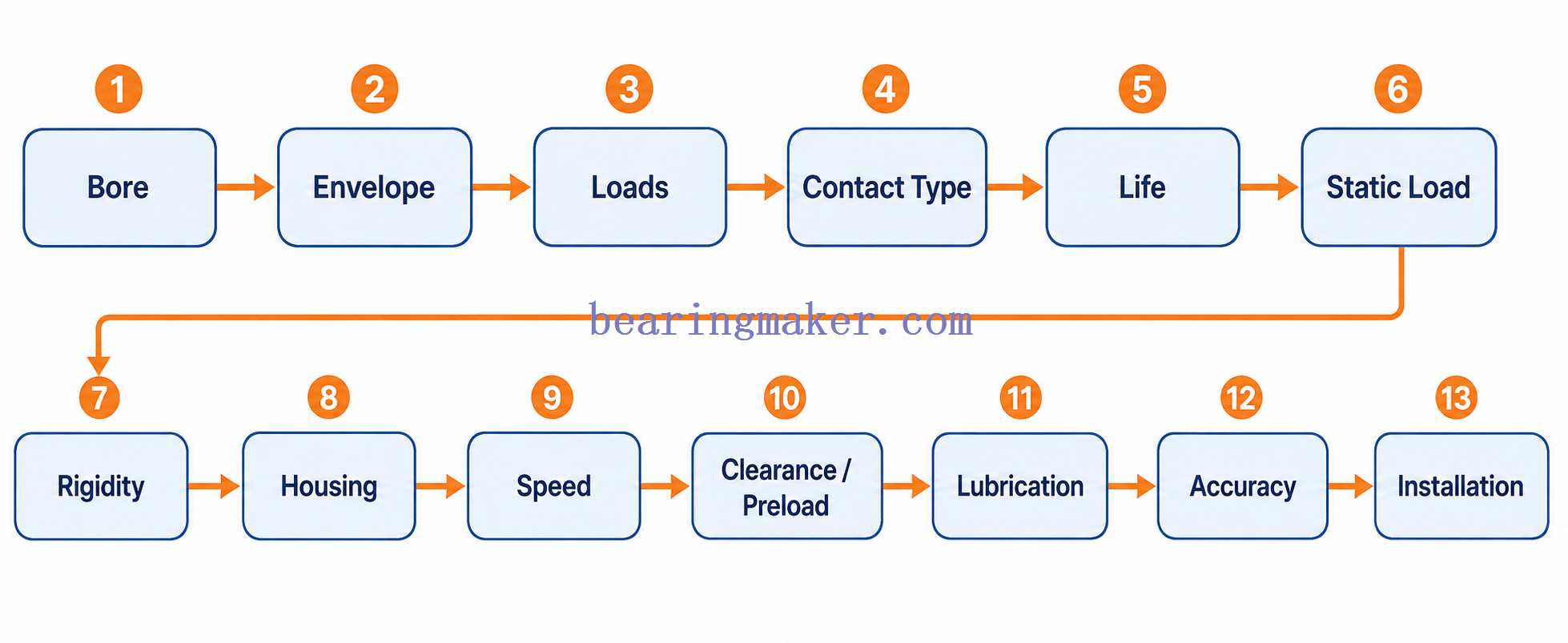
How to Choose a Thin Section Bearing
A good selection process begins with the complete machine requirements.
Step 1: Define the Required Bore
Start by determining how large the central opening must be.
Ask whether the bore must accommodate:
- shaft
- cables
- hoses
- optics
- other components
Step 2: Define the Maximum Outside Diameter
Determine the available radial envelope.
This defines the maximum allowable bearing cross-section.
Step 3: Identify Load Directions
Calculate:
- radial load
- axial load
- moment load
Do not ignore moment load simply because direct radial and axial forces appear small.
Step 4: Choose Contact Geometry
A practical starting point:
- mainly radial load → radial contact
- combined load with one-direction thrust → angular contact
- bidirectional axial + combined load → four-point contact
- high rigidity → paired angular contact or alternative high-rigidity design
Step 5: Check Dynamic Load Capacity
Estimate:
- equivalent dynamic load
- required L10 life
Verify that fatigue life meets the machine requirements.
Step 6: Check Static Load Capacity
Evaluate:
- stationary load
- shock
- impact
- transport loads
This can be especially important in precision machinery.
Step 7: Evaluate Moment Load
Moment load may create highly uneven ball loading.
The complete bearing arrangement should be evaluated rather than relying on radial and axial ratings alone.
Step 8: Determine Required Rigidity
Ask how much displacement is allowable under load.
A bearing can have adequate fatigue life but still be too flexible for the machine.
Step 9: Evaluate Housing and Shaft Stiffness
Check:
- wall thickness
- materials
- bolt pattern
- shaft deflection
- housing deformation
For thin section bearings, these are part of the bearing system.
Step 10: Determine Speed
Evaluate:
- RPM
- bearing diameter
- lubricant
- heat generation
- cage design
Step 11: Select Clearance or Preload
Choose according to:
- rigidity
- torque
- temperature
- precision
Avoid excessive preload.
Step 12: Choose Sealing and Lubrication
Balance:
- contamination protection
- friction
- speed
- maintenance
Step 13: Check Accuracy Requirements
Define:
- radial runout
- axial runout
- rotational accuracy
- repeatability
Remember that shaft and housing accuracy must support the bearing precision.
Step 14: Verify Installation Method
Review:
- fits
- shoulders
- mounting forces
- retention
- bolt loading
before finalizing the design.
Thin Section Bearing Selection Matrix
| Requirement | Common Starting Point |
|---|---|
| Maximum radial space saving | Thin section bearing |
| Predominantly radial load | Radial contact |
| One-direction axial + radial load | Angular contact |
| Bidirectional axial load | Four-point contact or opposed angular contact |
| Significant moment load | Four-point or paired angular contact |
| High precision + stiffness | Preloaded angular contact |
| Very high rigidity | Consider crossed roller |
| Corrosive environment | Corrosion-resistant material |
| Electrical insulation / selected high-speed use | Hybrid ceramic may be considered |
| Dirty environment | Sealed design |
| Low torque | Open or low-friction closure with suitable lubricant |
Common Thin Section Bearing Failure Modes
Thin section bearing failures often reveal problems in the surrounding machine structure.
1. Uneven Raceway Wear
Possible causes:
- housing distortion
- shaft misalignment
- poor shoulder squareness
- moment overload
Uneven wear usually indicates that the balls are not sharing load uniformly.
2. Excessive Running Torque
Possible causes:
- excessive preload
- too much interference
- housing deformation
- overgreasing
- seal friction
A sudden change in running torque may be an early warning sign.
3. Fatigue Spalling
Possible causes:
- excessive load
- contamination
- poor load distribution
- insufficient lubrication
4. Fretting
Fretting may occur between:
- inner ring and shaft
- outer ring and housing
when fits are too loose or micro-movement occurs under vibration.
5. Corrosion
Possible causes:
- moisture
- condensation
- chemical exposure
- unsuitable material
- poor sealing
6. Cage Damage
Possible causes include:
- high speed
- lubrication problems
- misalignment
- shock loading
- abnormal ball motion
7. Overheating
Possible causes:
- excessive preload
- overgreasing
- incorrect lubricant
- excessive speed
- distortion
- tight fits

Common Design Mistakes
Many thin section bearing problems originate during machine design.
Mistake 1: Selecting Only by Bore and Outside Diameter
A bearing may physically fit but still be wrong for:
- load
- moment
- stiffness
- speed
Mistake 2: Ignoring Moment Load
Large-diameter rotating assemblies can develop substantial overturning moments.
Moment load should be calculated explicitly.
Mistake 3: Treating Thin Rings Like Standard Bearing Rings
Thin rings are more sensitive to:
- shaft geometry
- housing geometry
- fits
The surrounding structure must provide proper support.
Mistake 4: Using Excessive Interference
Too much interference can reduce internal clearance and create unintended preload.
Mistake 5: Ignoring Housing Roundness
A high-precision bearing installed in an oval housing will not remain high precision.
Mistake 6: Excessive Preload
More preload does not automatically mean better precision.
Beyond the required value it mainly adds:
- heat
- torque
- stress
Mistake 7: Using Four-Point Contact as a Universal Solution
Four-point bearings are compact and versatile, but paired angular contact or crossed roller designs may provide better rigidity in demanding systems.
Mistake 8: Looking Only at Catalog Load Rating
Fatigue rating does not directly describe:
- system stiffness
- housing deformation
- moment behavior
- rotational accuracy
All of these may determine whether the application succeeds.
Maintenance and Condition Monitoring
Thin section bearings often operate in precision machinery, where early condition changes matter.
Monitor Running Torque
A gradual increase in torque can indicate:
- lubrication deterioration
- contamination
- preload change
- ring distortion
Monitor Temperature
Unexpected temperature increases may indicate:
- excess lubricant
- excess preload
- increased friction
- bearing damage
Monitor Vibration
Vibration can help identify:
- raceway damage
- imbalance
- structural looseness
- misalignment
Check Play and Stiffness
Increasing movement can indicate:
- wear
- loose fits
- preload loss
- structural movement
Inspect Seals and Lubricant
Look for:
- damaged seals
- lubricant leakage
- contamination
- corrosion
- grease deterioration
Thin Section Bearing Selection Checklist
Before choosing a thin section bearing, define the following:
| Parameter | What to Determine |
|---|---|
| Bore | Required shaft or hollow opening |
| Outside diameter | Maximum radial envelope |
| Cross-section | Available radial space |
| Radial load | Continuous + peak |
| Axial load | Magnitude + direction |
| Moment load | Maximum overturning moment |
| Speed | rpm |
| Required life | Hours or revolutions |
| Static load | Shock and stationary loads |
| Rigidity | Allowable displacement |
| Accuracy | Radial and axial runout |
| Housing stiffness | Material and geometry |
| Shaft stiffness | Deflection and roundness |
| Fit | Clearance or interference |
| Preload | Required/not required |
| Lubrication | Grease, oil, specialized |
| Sealing | Open, shielded, sealed |
| Temperature | Operating range |
| Environment | Dust, moisture, chemicals |
| Corrosion resistance | Required level |
| Maintenance | Access and service interval |
Frequently Asked Questions
What Is a Thin Section Bearing?
A thin section bearing is a rolling bearing designed with a relatively small cross-section compared with its bore diameter.
It provides a large central opening while minimizing radial space and weight.
What Is the Difference Between a Thin Section Bearing and a Normal Ball Bearing?
The main difference is the relationship between bore diameter and bearing cross-section.
Thin section bearings provide:
- larger bore relative to their section
- lower weight
- smaller radial envelope
However, their thinner rings are usually more sensitive to housing and shaft deformation.
Are Thin Section Bearings Weaker Than Standard Bearings?
For the same bore size, a thin section bearing will often have lower absolute load capacity than a much larger conventional bearing.
However, “weaker” is not necessarily the correct design comparison.
Thin section bearings are optimized for situations where:
- space
- weight
- large bore
- precision
are more important than maximizing load capacity within the same bore size.
Can Thin Section Bearings Carry Axial Loads?
Yes, depending on the contact geometry.
- radial contact designs carry mainly radial load with limited axial capability
- angular contact bearings support significant axial load in one direction
- four-point contact bearings can carry axial load in both directions
What Is a Four-Point Contact Thin Section Bearing?
A four-point contact bearing uses specially shaped raceways that allow the balls to support different load directions.
It can support combinations of:
- radial
- axial
- moment loads
within a compact single-bearing arrangement.
Can Thin Section Bearings Carry Moment Loads?
Yes, but moment capacity depends heavily on:
- bearing size
- contact geometry
- preload
- mounting structure
Four-point contact and paired angular contact arrangements are commonly used where moment loads are important.
Are Thin Section Bearings Suitable for High Speed?
Many thin section ball bearings offer good speed capability.
However, bearing diameter must be considered along with RPM.
A large-diameter bearing can experience high internal rolling-element velocities even at moderate shaft speed.
Why Are Thin Section Bearings Used in Robotics?
They provide an attractive combination of:
- large hollow bore
- low weight
- compact joint size
- low inertia
- precision rotation
The hollow bore is especially useful for routing cables and other services through the robot joint.
Thin Section Bearing or Crossed Roller Bearing: Which Is Better?
Neither is universally better.
Thin section ball bearings generally favor:
- low friction
- lower weight
- higher speed
Crossed roller bearings generally favor:
- higher rigidity
- greater moment stiffness
- smaller elastic displacement
The correct choice depends on the machine requirements.
Why Does Housing Accuracy Matter So Much?
Because thin bearing rings are relatively flexible.
If the housing is:
- oval
- distorted
- poorly supported
the outer ring may conform to that shape.
This alters raceway geometry and can cause uneven loading, higher torque, and reduced life.
Can Thin Section Bearings Be Preloaded?
Yes, particularly angular contact arrangements.
Preload can improve:
- stiffness
- accuracy
- repeatability
but excessive preload can increase heat and shorten service life.
Can Thin Section Bearings Be Sealed?
Yes.
Depending on design, they may be available or configured as:
- open
- shielded
- sealed
Sealing improves contamination protection but may increase friction.
Conclusion
Thin section bearings are not simply smaller versions of conventional ball bearings.
Their real engineering advantage is their ability to combine:
- a large bore
- small radial cross-section
- low weight
- compact rotary support
This makes them particularly valuable in robotics, aerospace, medical equipment, optical systems, semiconductor machinery, and precision automation.
But the reduced cross-section also changes the design priorities.
Thin rings are more sensitive to:
- housing distortion
- shaft geometry
- interference fits
- preload
- moment loading
- structural deflection
For this reason, thin section bearing selection should follow a system-level process:
Bore → Envelope → Load Direction → Moment Load → Contact Type → Fatigue Life → Static Load → Rigidity → Housing and Shaft Stiffness → Speed → Clearance or Preload → Lubrication → Accuracy → Installation
A correctly selected thin section bearing can reduce machine size and weight while maintaining precise, low-friction rotation.
A bearing selected only by dimensions and catalog load rating, however, may fail to deliver the required stiffness, torque, accuracy, or service life.
The most successful thin section bearing designs therefore treat the bearing, shaft, housing, preload, and mounting structure as a single mechanical system.


