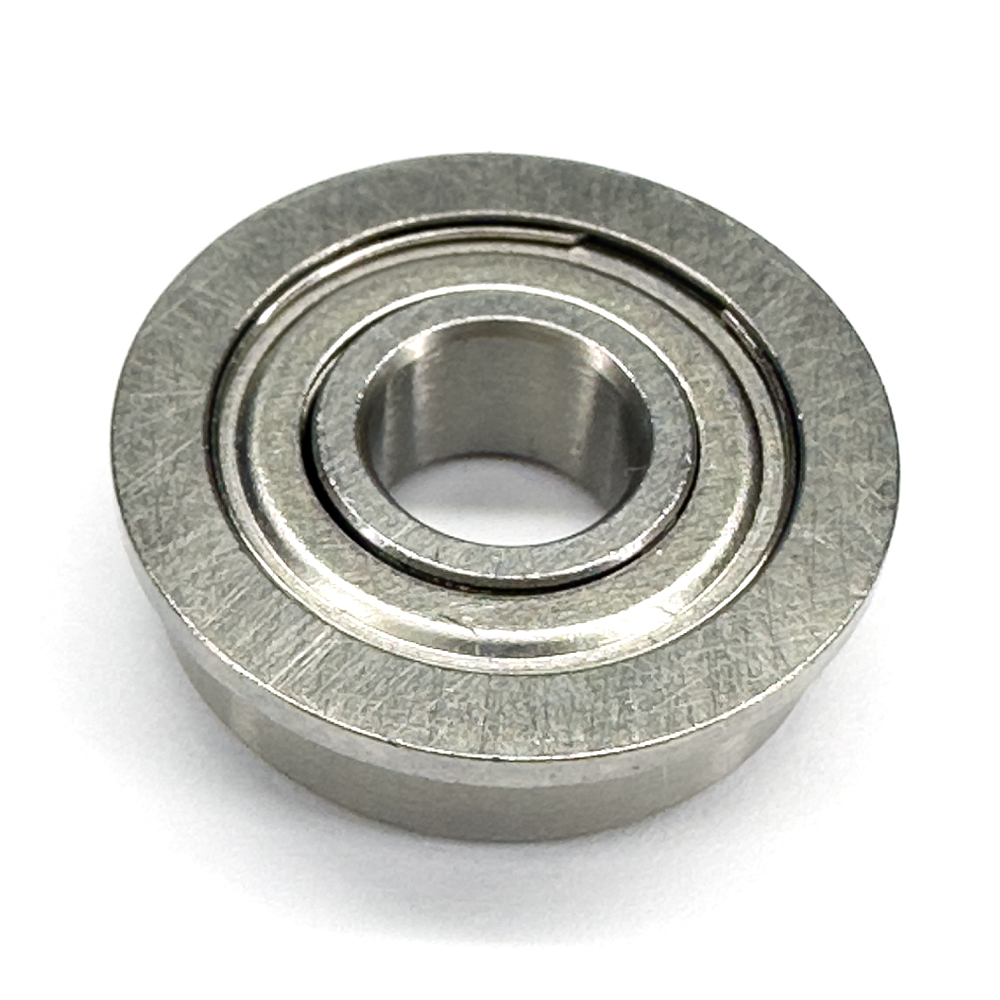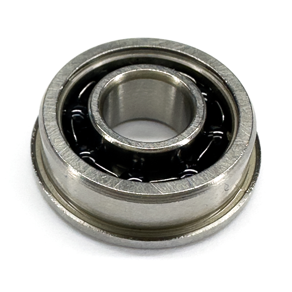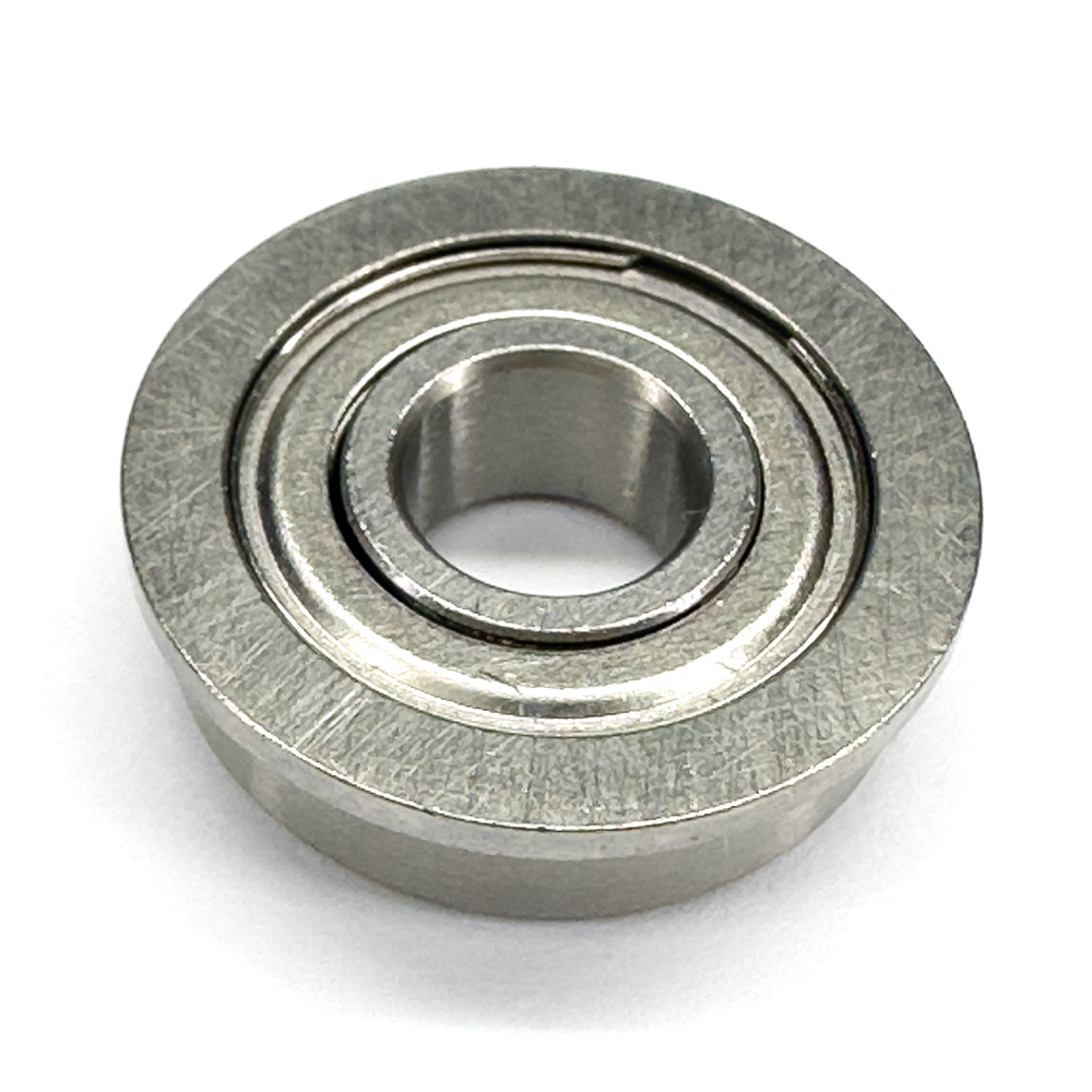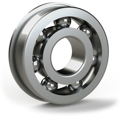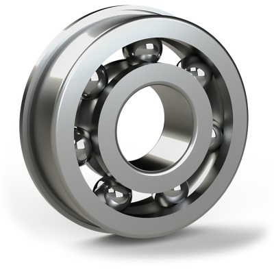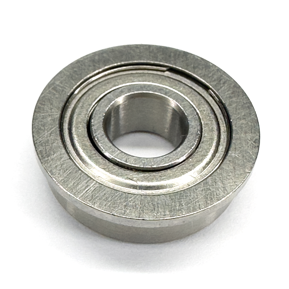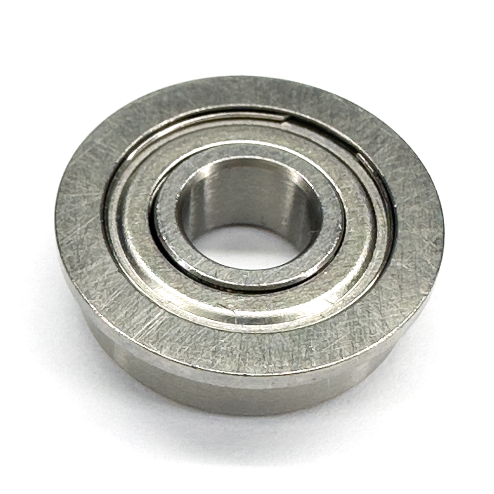
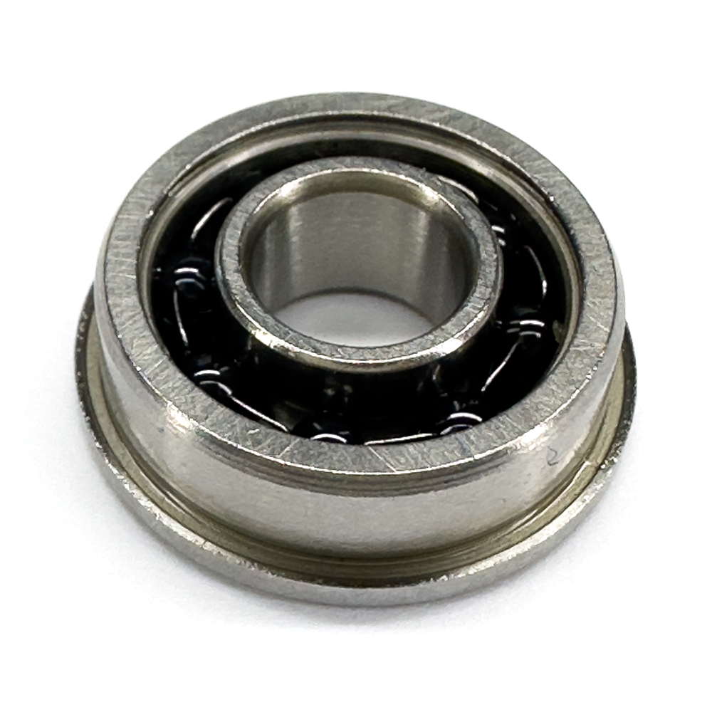
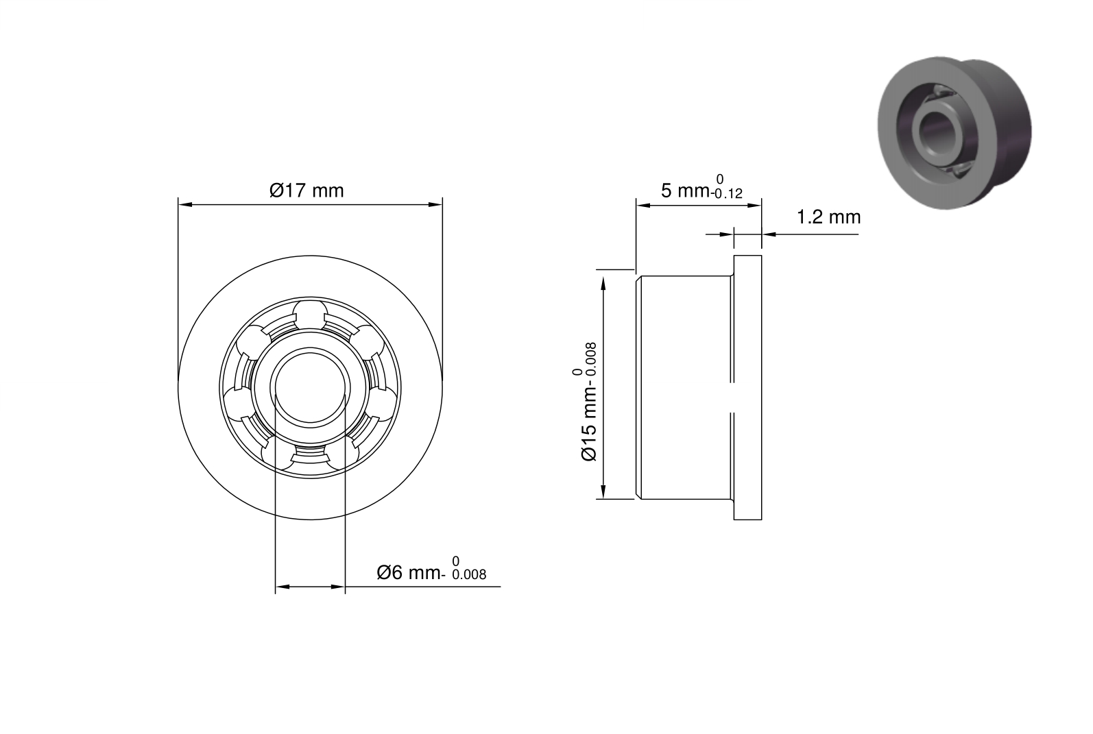
F696 is a standard flanged ball bearing. Its confirmed configuration is single row, open, and specified for radial loading. Selection depends on the interaction of its contact geometry, dimensional interfaces, component materials, enclosure, internal condition, and published operating data rather than on the model code or catalog family alone.
Construction and Load Path
F696 combines a radial ball-bearing load path with an outer-ring flange that provides a positive housing-side axial locating interface. The confirmed flange geometry is 17 mm outside diameter and 1.2 mm thickness. The flange locates the bearing; the main outside diameter remains the primary radial seating surface.
The housing should support the cylindrical outer-ring surface uniformly and provide clearance for the flange. Uneven clamping or force concentrated at the flange edge can tilt or distort the outer ring, so mounting-face flatness and shoulder geometry remain part of the bearing installation.
Dimensional Interfaces
The principal envelope for F696 is defined by bore 6 mm, outside diameter 15 mm, and width 5 mm. These dimensions must agree with the shaft, housing, shoulders, and available axial space as a coordinated set. They are interface controls, not isolated values to be matched independently.
The specified interface limits include bore tolerance -0.008mm to 0, outside diameter tolerance -0.008mm to 0, and width or height tolerance -0.12mm to 0. These limits support fit and stack-up evaluation but do not prescribe the finished shaft or housing fit. Ring rotation relative to load, mating-part material and stiffness, temperature change, and the required installed condition must be considered together.
Mounting and Structural Support
Installation of F696 should use clean, burr-free shaft and housing seats and apply force through the ring being fitted. Assembly force should not pass through the rolling elements, and the selected fit should account for ring rotation relative to load, mating-part stiffness, and temperature.
Shoulder squareness, seat roundness, concentricity, and uniform housing support influence alignment and running clearance. After mounting, free rotation, torque, noise, and temperature behavior can help identify binding, contamination, distortion, or unintended preload.
Component Materials
The fixed component specifications for F696 identify rings as Chrome Steel, rolling elements as Chrome Steel, and cage as Stainless Steel. Each value remains tied to its component role; ring material does not define ball, cage, seal, or shield material, and different materials may legitimately be specified for different components.
Component materials influence contact behavior, stiffness, thermal response, wear, lubricant compatibility, and environmental suitability. Those effects depend on the actual material pair, heat treatment, surface condition, lubricant, fits, load, speed, temperature, and exposure; no corrosion, electrical, chemical, food, medical, marine, or other application qualification is implied without explicit supporting data.
Precision, Clearance, and Tolerances
The listed internal-condition data for F696 include precision notation ABEC1, clearance designation MC3, and radial clearance 0.002mm to 0.013mm. The notation is retained exactly as supplied; no unsupported equivalence between ABEC, ISO, P-class, or manufacturer-specific terms is introduced.
Initial clearance and catalog precision do not describe the complete installed condition. Interference fits, ring temperature difference, shaft and housing geometry, shoulder runout, cleanliness, mounting force, and operating load can alter running clearance, alignment, torque, and contact distribution.
Load Ratings and Operating Data
The published radial ratings for F696 are 256 lbf dynamic and 94 lbf static. These values belong to different engineering checks: the dynamic rating supports rotating-fatigue evaluation, while the static rating is relevant to permanent-deformation risk under stationary, peak, or slowly moving load.
The operating data also provide maximum-speed entry 40 under the published ×1,000 rpm convention and temperature entry -30° to 110 °C. These are selection inputs, not independent guarantees of assembled performance. Fit, load, lubrication, closure drag, heat removal, alignment, and duty cycle determine whether the complete application can operate within the published conditions.
Enclosure and Lubrication
F696 is specified as open. The surrounding machine therefore controls lubricant retention and protection from contamination. Open construction does not establish dry-running capability, and the bearing should not be exposed to particles or fluids without an appropriate system-level enclosure.
The lubrication entry for F696 is Required. The application must establish lubricant type, quantity, delivery, and maintenance. This entry does not identify a particular grease or oil and must not be interpreted as a prelubricated condition.
Selection and Application Context
F696 may be considered for compact housings that benefit from a positive outer-ring axial locating face. These are general engineering contexts rather than certifications or guarantees of suitability. Final selection should verify load magnitude and direction, duty cycle, speed, temperature, lubrication, contamination exposure, required life, fits, and structural support.
The practical identity of F696 comes from the way its dimensions, contact geometry, component materials, closure, internal condition, and published operating data work together. A bearing with the same bore can behave differently when its width, outer diameter, row arrangement, enclosure, clearance, material configuration, or ratings differ.