Miniature bearings are small, precise components, but their performance depends heavily on the parts around them.
A bearing may have excellent:
- load capacity
- speed capability
- precision
- low torque
and still perform poorly if the shaft or housing is incorrectly designed.
Common problems include:
- excessive interference
- loose fits
- shaft bending
- poor roundness
- tilted shoulders
- housing misalignment
- installation damage
- adhesive contamination
- plastic housing deformation
These issues are especially important in miniature bearing systems because the bearing, shaft, and housing are all small.
A dimensional change of only a few micrometers may represent a meaningful percentage of:
- internal clearance
- ring thickness
- shaft diameter
The same is true for installation force.
A force that appears small to an assembler may be large relative to the rolling-element contact area.
For this reason, miniature bearing installation should be treated as a precision mechanical process rather than a simple press-fit operation.
This guide explains how to design the shaft and housing, choose suitable fits, control alignment, install miniature bearings without damage, and verify the final assembly.
Why Fits Matter in Miniature Bearings
The fit determines how the inner and outer rings connect to:
- shaft
- housing
The fit must be strong enough to prevent unwanted movement but not so tight that it distorts the bearing or removes too much internal clearance.
This creates a basic design balance:
retention vs. internal geometry
What Happens When a Bearing Is Installed?
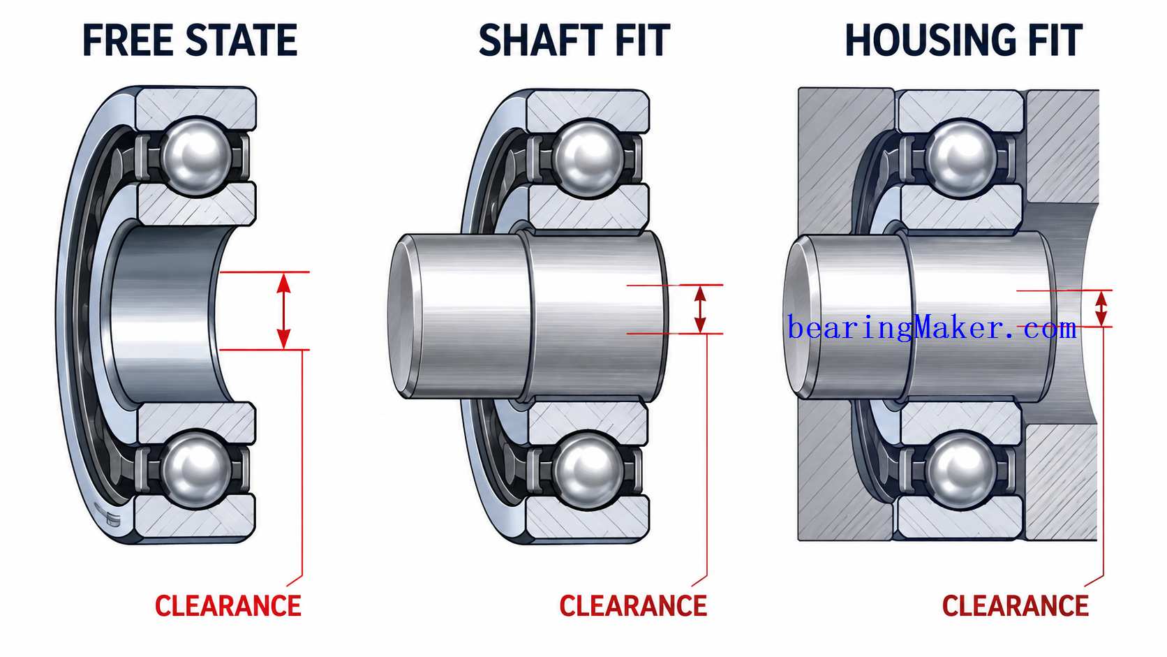
The bearing geometry changes slightly after mounting.
An interference fit can cause:
- inner-ring expansion
- outer-ring compression
These dimensional changes reduce internal clearance.
If the original clearance is already small, installation can convert the bearing into a preloaded condition.
This may increase:
- stiffness
- torque
- heat
If the change is excessive, bearing life may decrease.
Shaft Fit
The inner ring usually mounts directly on the shaft.
Important shaft properties include:
- diameter
- roundness
- cylindricity
- straightness
- surface finish
- stiffness
Each can affect bearing behavior.
Shaft Diameter Tolerance
Shaft diameter determines the actual fit between:
- shaft
- bearing bore
If the shaft is too small:
- the inner ring may creep
- positioning may be unstable
If the shaft is too large:
- the inner ring expands excessively
- internal clearance decreases
Why Small Diameter Errors Matter
Suppose a shaft is only a few millimeters in diameter.
A small dimensional error represents a larger percentage of the shaft diameter than the same error would in a large industrial shaft.
This makes manufacturing consistency particularly important.
Clearance Fit on the Shaft
A clearance fit allows some dimensional space between:
- shaft
- inner ring
Advantages can include:
- easy assembly
- low risk of fit-induced preload
Potential disadvantages include:
- ring movement
- creep
- fretting
- lower positional stability
Interference Fit on the Shaft
An interference fit requires the inner ring to expand over the shaft.
Advantages include:
- strong retention
- reduced risk of creep
Potential disadvantages include:
- reduced internal clearance
- higher torque
- higher preload
Which Ring Needs the Tighter Fit?
The answer depends partly on how the load rotates relative to the ring.
A ring exposed to a rotating load generally requires stronger retention than one exposed to a stationary load.
However, fit selection should also consider:
- bearing size
- operating temperature
- desired clearance
- assembly method
There is no universal miniature bearing fit that is correct for every application.
Inner-Ring Expansion
When the inner ring is pressed onto a shaft, it expands elastically.
This can change:
- raceway diameter
- internal clearance
In a miniature bearing, a small ring expansion may be large relative to the original clearance.
Why Excessive Shaft Interference Is Dangerous
Too much interference can create:
- unintended preload
- high starting torque
- overheating
In high-speed miniature motors, this can become a major reliability problem.
Housing Fit
The outer ring usually fits into a housing bore.
Important housing characteristics include:
- diameter
- roundness
- concentricity
- stiffness
- material
Housing Bore Tolerance
If the housing bore is too large:
- the outer ring may move
- accuracy may decrease
If the bore is too small:
- the outer ring may compress
- internal clearance may decrease
Outer-Ring Compression
A tight housing fit can compress the outer ring.
The effect may be small in absolute terms but still significant at miniature scale.
Loose Housing Fit
A loose fit may be acceptable in some low-load arrangements.
However, possible risks include:
- creep
- fretting
- noise
- positional instability
Interference in the Housing
A housing interference fit can provide strong retention.
But excessive interference may cause:
- ring compression
- higher torque
- reduced clearance
Bearing Fit and Internal Clearance
The actual operating clearance can be thought of conceptually as:
initial clearance − shaft-fit effect − housing-fit effect − thermal effect
The final value may be:
- positive clearance
- near zero
- preload
Why Fit and Clearance Must Be Selected Together
A bearing cannot be selected by clearance independently of the mounting fits.
For example, a bearing with suitable free-state clearance may become too tight after both rings are installed with interference.
Shaft Roundness
The shaft should be sufficiently round.
An out-of-round shaft can distort the inner ring.
Possible effects include:
- torque variation
- runout
- uneven ball loading
Shaft Cylindricity
A shaft may have correct average diameter but still be:
- tapered
- barrel-shaped
- hourglass-shaped
These errors can create uneven support along the inner-ring width.
Shaft Straightness
A bent shaft can misalign two bearings.
This may create:
- uneven load
- increased torque
- vibration
Why Shaft Straightness Matters More With Two Bearings
When a shaft is supported by two miniature bearings, both bearing centers should lie on the same rotational axis.
A bent shaft forces the bearings into angular misalignment.
Shaft Surface Finish
Surface finish affects:
- fit consistency
- seating
A rough shaft may produce irregular contact and difficult assembly.
Shaft Stiffness
Miniature bearings often use very small shafts.
The shaft can therefore become a major structural limitation.
Why Shaft Stiffness Can Matter More Than Bearing Capacity
A bearing may safely carry the radial load.
But if the shaft bends significantly, the bearing may become misaligned.
This can create:
- uneven internal loading
- higher vibration
- reduced life
Shaft Bending
Shaft bending can result from:
- overhung gears
- pulleys
- fans
- impellers
The greater the distance between the load and the nearest bearing, the greater the bending effect.
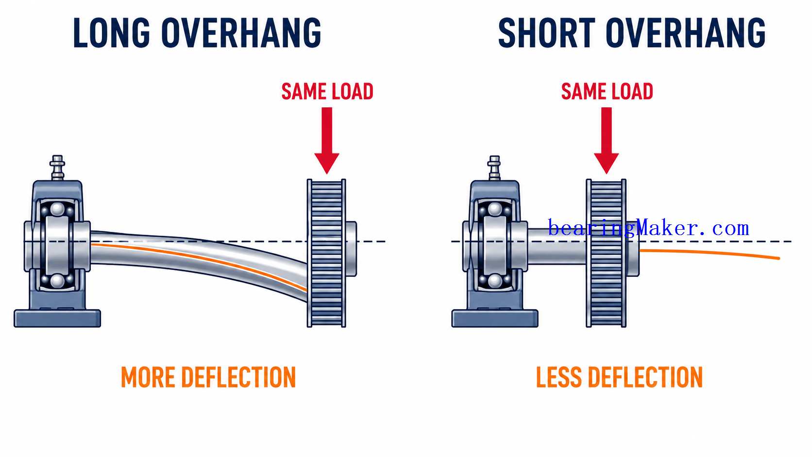
Reduce Overhung Distance
One of the simplest ways to improve shaft stiffness is to place:
- gear
- pulley
- fan
closer to the bearing.
This reduces bending moment.
Bearing Spacing
Two bearings separated by a greater axial distance can provide better angular support.
Greater spacing may reduce:
- shaft tilt
- moment sensitivity
But it also increases:
- assembly length
Two-Bearing Alignment
When two miniature bearings support one shaft, their seats should be sufficiently:
- concentric
- coaxial
Misaligned bearing seats can force the shaft into bending.
Housing Concentricity
If two housing bores are not coaxial, the outer rings may be positioned on different axes.
This can create:
- bearing misalignment
- friction
- heat
Shoulder Design
Bearing shoulders locate the rings axially.
A good shoulder should provide:
- flat support
- correct squareness
- suitable contact area
Shaft Shoulder
The shaft shoulder locates the inner ring.
Important characteristics include:
- squareness
- height
- corner radius
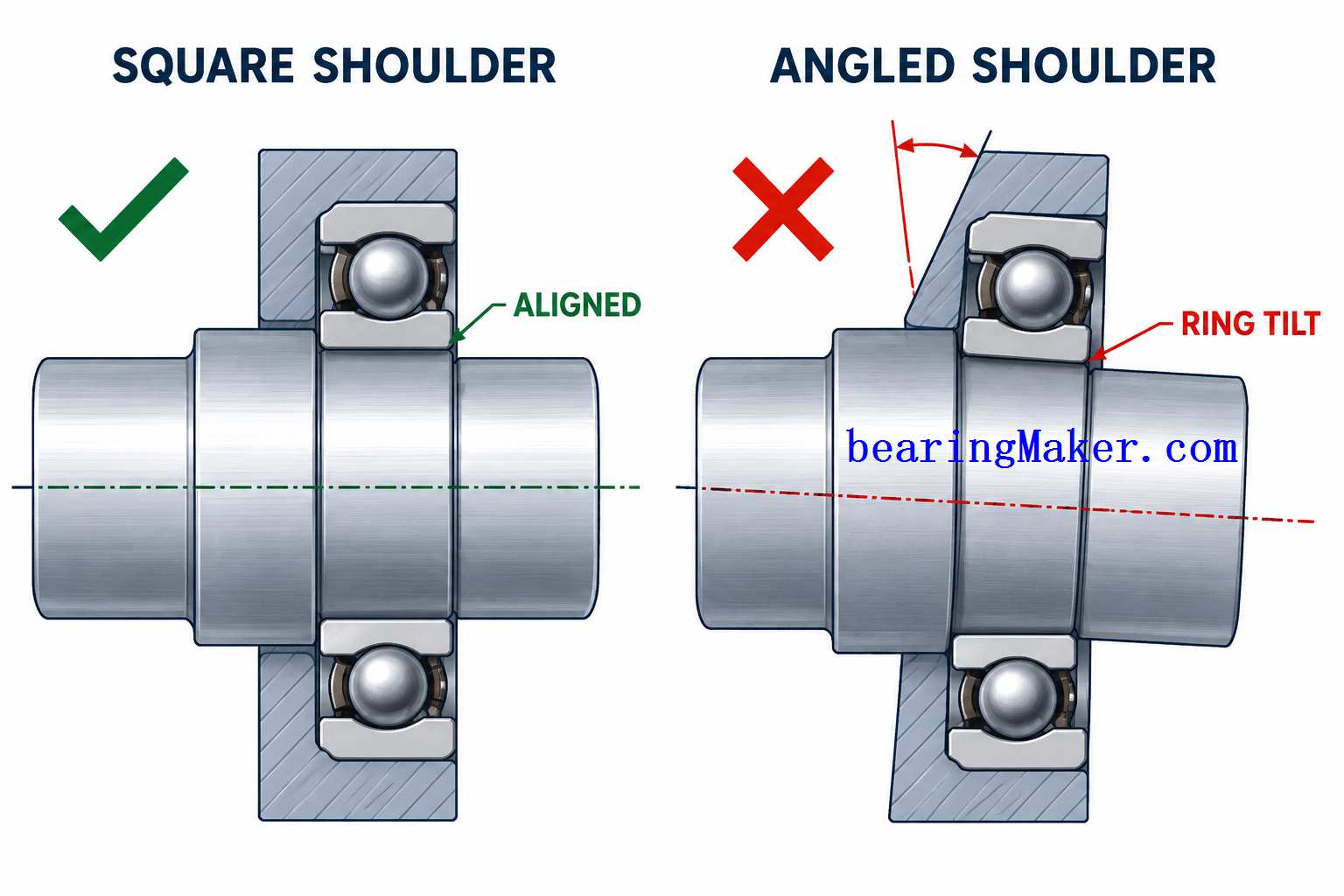
Shoulder Squareness
If the shoulder is not square to the shaft axis, the inner ring can tilt.
This may cause:
- axial runout
- uneven load
- high torque
Housing Shoulder
The housing shoulder supports the outer ring axially.
It should also be:
- flat
- square
Shoulder Contact Area
The shoulder should contact the ring face properly without interfering with:
- seals
- shields
- ring chamfers
Shoulder Radius
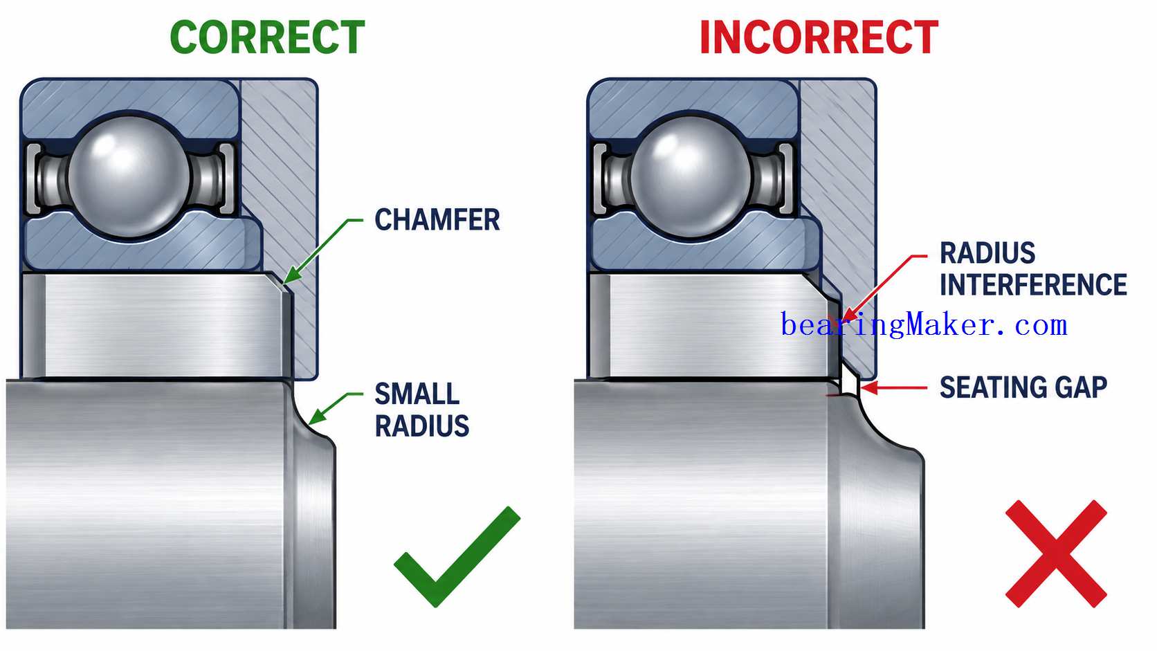
Shaft and housing shoulders often include a corner radius.
If the radius is too large, it may interfere with the bearing ring chamfer.
The ring may then fail to seat fully against the shoulder.
Why Chamfer Compatibility Matters
A bearing may appear installed but actually rest on:
- shaft radius
- housing radius
instead of the intended shoulder face.
This can cause:
- tilt
- axial position error
- runout
Flanged Miniature Bearings
Flanged miniature bearings can simplify axial location.
The outer-ring flange rests against the housing face.
Advantages include:
- simple housing geometry
- easier positioning
- reduced need for internal shoulders
Flange Face Support
The housing face supporting the flange should be:
- flat
- square
A warped surface can tilt the bearing.
Flange Retention
The flange should not be clamped so aggressively that the outer ring becomes distorted.
Axial Retention
Bearing rings may be retained axially using:
- shoulders
- retaining rings
- clamp plates
- adhesives
The correct method depends on:
- load
- available space
- precision
Retaining Rings
Retaining rings can provide simple axial location.
Potential limitations include:
- axial play
- groove tolerance
- assembly complexity at very small size
Clamp Plates
A small clamp plate can retain the outer ring.
However, uneven clamping can:
- tilt
- distort
the bearing.
Threaded Retainers
Threaded retainers may provide controlled axial positioning.
But excessive tightening can introduce:
- unwanted preload
Adhesive Retention
Adhesive is sometimes used in miniature bearing assemblies where mechanical interference is undesirable.
This can be useful in:
- thin housings
- plastic housings
- delicate precision mechanisms
Advantages of Adhesive Retention
Potential benefits include:
- reduced mechanical interference
- simplified assembly
- improved retention in loose housings
Risks of Adhesive Retention
Possible problems include:
- adhesive entering the bearing
- uneven bond thickness
- misalignment during curing
- future service difficulty
Keep Adhesive Away From Rolling Components
Adhesive should not enter:
- seals
- shields
- raceways
Even a very small amount can create:
- high torque
- contamination
- bearing lockup
Adhesive Gap
Adhesive systems often require a suitable bond-line thickness.
A fit that is too tight may leave insufficient adhesive.
A fit that is too loose may make alignment difficult.
Plastic Housings
Miniature bearings are frequently mounted in molded plastic housings.
Applications include:
- fans
- consumer electronics
- small motors
- instruments
Plastic behaves differently from metal.
Plastic Housing Advantages
Advantages can include:
- low cost
- low weight
- integrated geometry
- high-volume manufacturability
Plastic Housing Challenges
Potential issues include:
- lower stiffness
- thermal expansion
- molding shrinkage
- long-term creep
Molding Shrinkage
The final housing bore may differ from the nominal mold geometry due to:
- material shrinkage
- process variation
This can produce inconsistent bearing fits.
Plastic Creep
Over time, plastic under stress can deform.
A press-fit bearing may gradually become:
- looser
This may cause:
- movement
- noise
- loss of alignment
Thermal Expansion of Plastic
Plastic housings often expand more with temperature than metallic bearing rings.
The fit may therefore change significantly as temperature changes.
Why Room-Temperature Fit Is Not Enough
A bearing may fit correctly during assembly but become:
- loose when hot
- tight when cold
depending on the material system.
Flanged Bearings in Plastic Housings
Flanged miniature bearings can simplify mounting because the flange provides:
- axial position
- face reference
This can reduce dependence on a molded internal shoulder.
Metal Housings
Metal housings generally provide:
- greater stiffness
- better dimensional stability
Possible materials include:
- aluminum
- steel
- brass
Aluminum Housings
Aluminum is lightweight and easy to machine.
However, it expands more with temperature than steel bearing rings.
This can change the outer-ring fit during operation.
Steel Housings
Steel generally offers:
- high stiffness
- dimensional stability
but adds weight.
Temperature and Fit
Temperature changes the dimensions of:
- shaft
- bearing rings
- housing
The operating fit may therefore differ from the assembly fit.
Thermal Expansion of the Shaft
If the shaft expands more than the inner ring, interference may increase.
This can reduce clearance.
Thermal Expansion of the Housing
If the housing expands more than the outer ring, the outer-ring fit may loosen.
Thermal Gradients
The shaft and inner ring may be hotter than the housing.
This can reduce internal clearance even if all components are made from similar materials.
Cold-Start Conditions
At low temperature:
- fits may change
- lubricant becomes more viscous
A bearing that is already tightly fitted may show particularly high starting torque.
Installation Methods
Miniature bearings may be installed using:
- press mounting
- thermal mounting
- adhesive mounting
- hand assembly for clearance fits
The correct method depends on:
- fit
- size
- available tooling
Press Installation
Press installation is common for interference fits.
The key requirements are:
- apply force to the correct ring
- keep the bearing square
- use controlled force
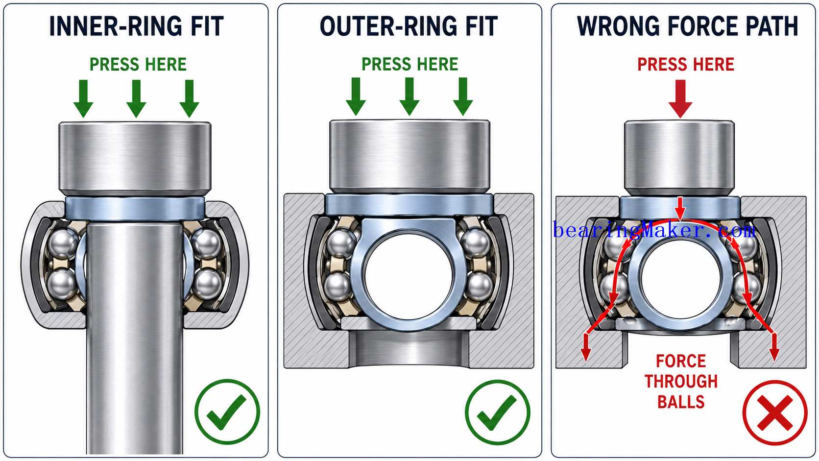
Apply Force to the Fitted Ring
If the inner ring has the interference fit:
- press on the inner ring
If the outer ring has the interference fit:
- press on the outer ring
Why Force Through the Balls Is Dangerous
If force passes through:
- ring
- balls
- opposite ring
the rolling elements can indent the raceways.
This can cause:
- brinelling
- noise
- vibration
- shortened life
Simultaneous Fitting of Both Rings
If both rings must be installed simultaneously, tooling should ideally apply force to both rings without transmitting unnecessary force through the rolling elements.
Installation Tooling
Good tooling should:
- contact the intended ring
- stay square
- distribute force evenly
Avoid Point Loading
A narrow tool or screwdriver can apply highly concentrated force.
This may:
- damage the ring
- deform shields or seals
Avoid Hammering
Impact installation can create:
- brinelling
- ring damage
- misalignment
Controlled pressing is preferred.
Keep the Bearing Square During Installation
If the bearing enters at an angle, it may:
- jam
- score the shaft or housing
- distort
Thermal Installation
Thermal mounting changes component dimensions temporarily to reduce required installation force.
Possible methods include:
- warming the inner ring
- cooling the shaft
- cooling the outer ring
depending on the fit direction.
Thermal Mounting Advantages
Benefits may include:
- lower press force
- reduced risk of mechanical damage
Thermal Mounting Risks
Excessive or uneven temperature can damage:
- lubricant
- seals
- cage
Thermal methods should therefore be controlled.
Do Not Overheat Pre-Lubricated Bearings
Pre-lubricated miniature bearings may contain:
- grease
- polymer seals
High temperature can damage these components.
Cleanliness During Installation
Cleanliness is critical.
Miniature bearings have small:
- clearances
- contact zones
A small particle can create:
- noise
- roughness
- premature damage
Clean Shaft and Housing Seats
Before assembly, remove:
- machining chips
- dust
- dried lubricant
- burrs
Avoid Touching Critical Surfaces
Contamination from hands can introduce:
- oils
- particles
- moisture
Precision applications may require controlled handling.
Burrs and Edge Damage
Burrs on a shaft or housing can:
- scratch rings
- prevent proper seating
- create misalignment
Edges should be prepared before installation.
Assembly Sequence
The order of assembly can affect final bearing condition.
For example:
- inner ring mounted on shaft
- shaft inserted into housing
- second bearing installed
- cover tightened
Each step may alter:
- alignment
- preload
Why Final Assembly Condition Matters
A bearing may rotate freely before the housing cover is tightened.
After final tightening, torque may increase due to:
- misalignment
- excessive axial clamping
Final checks should therefore be performed after complete assembly.
Two-Bearing Assembly
Two miniature bearings on one shaft require particular care.
The system must avoid forcing both bearings into incompatible positions.
Fixed and Floating Arrangements
In some designs, one bearing locates the shaft axially while the other allows small axial movement.
This can help accommodate:
- thermal expansion
- manufacturing tolerance
Why Two Rigid Axial Locations Can Be Problematic
If both bearings are rigidly constrained and the shaft expands thermally, internal axial load may increase.
Spring-Preloaded Arrangements
A spring may apply controlled axial preload to one bearing.
This can help:
- remove play
- accommodate thermal expansion
Rigid Spacer Arrangements
Rigid spacers can provide:
- precise bearing spacing
but require careful control of:
- dimensions
- shoulder positions
Misalignment
Misalignment occurs when the inner and outer ring axes are not properly aligned.
Possible causes include:
- bent shaft
- non-coaxial housing
- tilted shoulders
- installation error
Effects of Misalignment
Misalignment can create:
- uneven contact
- higher friction
- heat
- vibration
- reduced life
Deep Groove Miniature Bearings Are Not Self-Aligning
Their small size should not be interpreted as tolerance for poor alignment.
Ring Creep
Ring creep occurs when a bearing ring moves relative to:
- shaft
- housing
This can occur when the fit is insufficient for the load condition.
Effects of Creep
Possible consequences include:
- wear
- fretting
- loss of precision
- heat
Fretting
Fretting is small repeated movement at the interface.
It may create:
- dark or reddish debris
- polished surfaces
Why Increasing Interference Is Not Always the Answer
If creep occurs, simply increasing interference aggressively can create:
- bearing distortion
- preload
The correct fix may instead involve:
- better surface design
- adhesive retention
- different fit strategy
Installation-Induced Brinelling
Incorrect assembly force can permanently indent the raceway.
The bearing may then show:
- periodic vibration
- noise
even though it is new.
Shield and Seal Damage During Installation
Installation tooling should not contact:
- shields
- seals
These components can be easily:
- bent
- displaced
Bent Shields
A bent shield may rub against:
- inner ring
- cage
causing high torque or noise.
Damaged Seals
A damaged seal may cause:
- increased drag
- contamination entry
- lubricant leakage
Post-Installation Checks
A miniature bearing should not simply be installed and forgotten.
Useful checks include:
- free rotation
- running torque
- axial play
- radial runout
- axial runout
- noise
Hand Rotation Check
Where appropriate, gently rotate the shaft after installation.
Check for:
- roughness
- binding
- periodic resistance
Starting Torque Check
If the system is torque-sensitive, measure:
- breakaway torque
after final assembly.
Running Torque Check
Compare running torque with:
- expected value
- known-good baseline
A major increase after assembly may indicate:
- excessive fit
- preload
- misalignment
Torque Variation
If torque rises and falls periodically during one revolution, possible causes include:
- shaft eccentricity
- housing distortion
- bearing damage
Radial Runout Check
Radial runout can reveal:
- shaft error
- bearing eccentricity
- housing error
Axial Runout Check
Axial runout can reveal:
- shoulder tilt
- bearing tilt
- face error
Noise Check
Unexpected noise after installation may indicate:
- contamination
- raceway damage
- shield rubbing
- preload
Temperature Check
During initial operation, monitor temperature.
Rapid temperature rise can indicate:
- high preload
- tight fit
- misalignment
- excessive grease
Before-and-After Torque Comparison
A useful diagnostic method is to measure torque:
- bearing before installation
- after shaft fit
- after housing fit
- after final axial retention
The point where torque increases can identify the source of the problem.
Measuring Shaft Runout
Shaft runout can be checked with:
- dial indicator
- displacement sensor
Measure near the bearing and at the working end of the shaft.
Why Measurement Location Matters
A shaft may have small runout near the bearing but much larger displacement farther away if:
- shaft is bent
- bearing is tilted
Housing Bore Measurement
Housing bore checks may include:
- diameter
- roundness
- concentricity
For plastic housings, measurements may need to consider:
- temperature
- molded variation
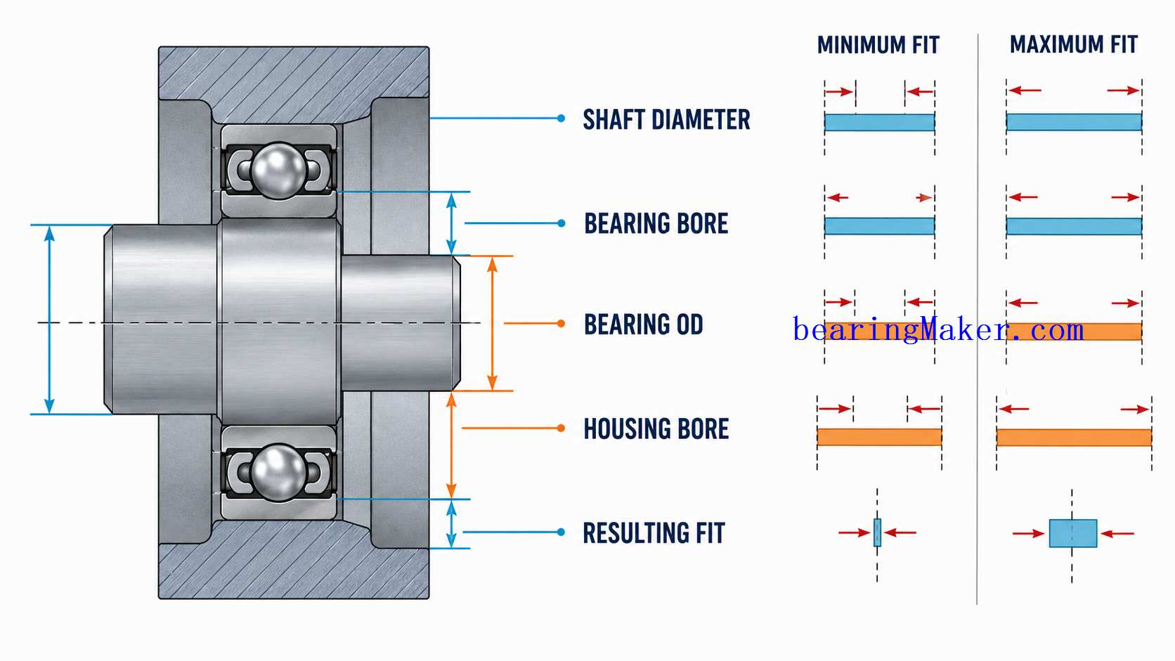
Tolerance Stack-Up
Bearing mounting involves multiple tolerances:
- bearing bore
- shaft diameter
- bearing OD
- housing bore
- shoulders
- spacers
The worst-case combination may create a very different fit from the nominal design.
Design for Manufacturing
Miniature bearing design should reflect actual manufacturing capability.
A fit requiring extremely tight machining may be difficult to reproduce economically in high-volume production.
Design for Assembly
The design should make it difficult to install the bearing incorrectly.
Useful features include:
- clear shoulders
- guided press tools
- flanges
- assembly stops
Design for Service
If the bearing may require replacement, consider whether the assembly allows removal without:
- damaging shaft
- housing
- bearing seat
High-Volume Production
In mass production, bearing performance depends on variation across:
- shafts
- housings
- bearings
- assembly force
The nominal prototype fit may not represent the production extremes.
Statistical Variation
Production should consider the distribution of:
- shaft diameters
- housing bores
rather than only one nominal value.
Plastic Housing Production Variation
Molding conditions can change:
- shrinkage
- bore size
- roundness
Process control becomes important.
Miniature Motor Fit Example
Consider a small electric motor with two miniature bearings.
Important design factors include:
- shaft diameter
- end-cap housing bore
- bearing spacing
- preload
If one housing bore is misaligned, the shaft may bend slightly.
The result may be:
- higher current
- noise
- temperature
even though both bearings are individually good.
Cooling Fan Fit Example
A cooling fan may use:
- molded plastic housing
- small shaft
- miniature bearings
Possible long-term issues include:
- plastic creep
- lubricant aging
- fit loosening
The initial assembly should therefore be evaluated over the expected temperature and service life.
Precision Instrument Fit Example
A precision instrument may require:
- very low runout
- very low torque
Heavy interference may be undesirable.
Possible strategies may include:
- light fits
- adhesive retention
- careful axial preload
Miniature Pump Fit Example
A pump may create:
- radial load
- axial thrust
- moisture exposure
Fits should provide secure retention while material and sealing address the environment.
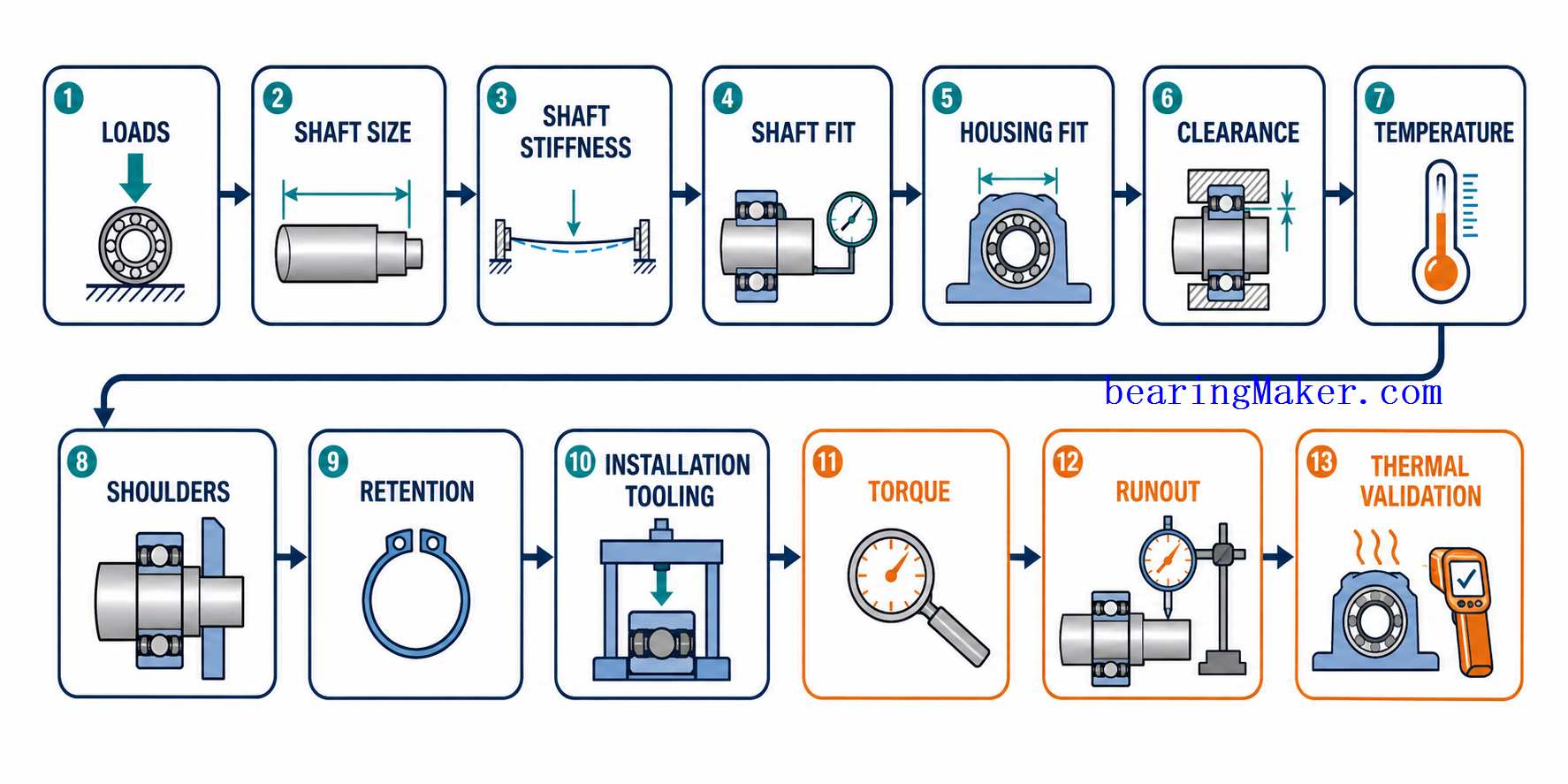
Practical Shaft and Housing Design Workflow
Step 1: Define Bearing Loads
Identify:
- radial load
- axial load
- shock
Step 2: Select Bearing Bore
Choose a bore compatible with required shaft:
- strength
- stiffness
Step 3: Check Shaft Deflection
Evaluate:
- overhung loads
- bearing spacing
Step 4: Define Shaft Tolerance
Select the fit based on:
- load condition
- required internal clearance
Step 5: Define Housing Material
Identify:
- metal
- plastic
- composite
Step 6: Define Housing Tolerance
Specify:
- bore size
- roundness
- concentricity
Step 7: Evaluate Fit-Induced Clearance Change
Estimate how:
- inner-ring expansion
- outer-ring compression
change bearing clearance.
Step 8: Evaluate Temperature
Check:
- minimum temperature
- operating temperature
- maximum temperature
Step 9: Design Shoulders
Specify:
- flatness
- squareness
- radius compatibility
Step 10: Select Axial Retention
Choose:
- shoulder
- flange
- retaining ring
- adhesive
- clamp
Step 11: Define Installation Method
Select:
- press
- thermal
- adhesive
Step 12: Design Installation Tooling
Ensure force reaches the correct ring.
Step 13: Define Assembly Cleanliness
Control:
- dust
- chips
- adhesive
Step 14: Assemble and Check Torque
Measure:
- starting torque
- running torque
Step 15: Measure Runout
Check:
- radial
- axial
Step 16: Validate Under Operating Temperature
Recheck:
- torque
- noise
- alignment
after thermal stabilization.
Common Shaft and Installation Mistakes
Mistake 1: Choosing the Smallest Possible Shaft
The shaft may become too flexible.
Mistake 2: Using Excessive Interference
This can eliminate internal clearance.
Mistake 3: Using a Loose Fit Without Considering Creep
The ring may move relative to the shaft or housing.
Mistake 4: Ignoring Shaft Roundness
An out-of-round shaft can distort the inner ring.
Mistake 5: Ignoring Shoulder Radius
The ring may fail to seat against the intended face.
Mistake 6: Pressing Through the Balls
This can cause permanent raceway damage.
Mistake 7: Hammering the Bearing Into Place
Impact can produce:
- brinelling
- misalignment
Mistake 8: Pressing on a Shield or Seal
This can deform the closure.
Mistake 9: Ignoring Plastic Creep
A fit that is correct initially may loosen over time.
Mistake 10: Using Adhesive Without Controlling Flow
Adhesive can contaminate the bearing.
Mistake 11: Ignoring Assembly Sequence
Final clamping may change preload or alignment.
Mistake 12: Checking Torque Before Final Assembly Only
The bearing may become tight after the last component is installed.
Troubleshooting High Torque After Installation
Possible causes include:
- excessive shaft interference
- tight housing fit
- excessive axial preload
- misalignment
- damaged seal or shield
Troubleshooting Periodic Torque Variation
Possible causes include:
- shaft runout
- bearing tilt
- housing eccentricity
- raceway damage
Troubleshooting Bearing Creep
Check:
- shaft or housing diameter
- rotating load condition
- temperature
- surface condition
Troubleshooting Fretting
Possible causes include:
- loose fit
- vibration
- repeated micro-motion
Troubleshooting Excessive Runout
Check:
- shaft straightness
- shoulder squareness
- housing concentricity
- trapped contamination
Troubleshooting Noise After Installation
Possible causes include:
- installation brinelling
- contamination
- misalignment
- shield rubbing
- excessive preload
Troubleshooting Heat After Assembly
Possible causes include:
- tight fit
- preload
- misalignment
- excessive grease
Fit and Installation Troubleshooting Matrix
| Symptom | Possible Cause | What to Check |
|---|---|---|
| High starting torque | Tight fit/preload | Shaft, housing, axial clamp |
| High running torque | Misalignment/interference | Coaxiality, fit |
| Periodic torque | Runout/distortion | Shaft, housing |
| Bearing creep | Fit too loose | Interface dimensions |
| Fretting | Micro-movement | Fit, vibration |
| High radial runout | Shaft/housing error | Geometry |
| High axial runout | Shoulder tilt | Shoulder squareness |
| Noise after pressing | Brinelling | Installation force path |
| Shield rubbing | Tool damage | Shield condition |
| Fit loosens over time | Plastic creep | Housing material |
| Bearing binds when hot | Thermal fit change | Expansion, clearance |
| Bearing binds after cover install | Axial clamping/misalignment | Assembly sequence |
Frequently Asked Questions
What Fit Should Be Used for a Miniature Bearing?
There is no universal fit.
The correct fit depends on:
- load direction
- ring rotation
- bearing clearance
- material
- temperature
Should the Inner Ring Always Have an Interference Fit?
No.
It depends on the operating load and retention requirement.
Can an Interference Fit Damage a Miniature Bearing?
Excessive interference can reduce internal clearance and increase:
- torque
- heat
Why Does My Bearing Become Tight After Pressing It Onto the Shaft?
The inner ring may have expanded enough to reduce internal clearance.
Can the Housing Fit Also Reduce Clearance?
Yes.
Outer-ring compression can reduce internal clearance.
Why Is Shaft Roundness Important?
The inner ring can follow an out-of-round shaft, changing:
- runout
- torque
- load distribution
Why Is Shaft Stiffness Important?
Small shafts can bend easily.
Shaft bending may misalign the bearing even when bearing load capacity is adequate.
How Can I Reduce Shaft Deflection?
Possible methods include:
- larger shaft diameter
- shorter overhang
- greater bearing spacing
Should I Press a Bearing by the Inner or Outer Ring?
Apply force to the ring that has the interference fit.
Why Should Installation Force Not Pass Through the Balls?
It can indent the raceways and cause permanent damage.
Can I Hammer a Miniature Bearing Into Place?
Impact installation is generally undesirable because it can damage:
- raceways
- rings
Controlled pressing is preferable.
Can Adhesive Be Used to Retain a Miniature Bearing?
Yes, in suitable designs.
But adhesive must be controlled carefully to prevent contamination and misalignment.
Are Plastic Housings Suitable for Miniature Bearings?
Yes.
They are widely used, but designers should consider:
- creep
- thermal expansion
- molding variation
Why Does a Plastic Housing Fit Become Loose Over Time?
Long-term stress and temperature can cause plastic creep.
Can a Flanged Bearing Simplify Installation?
Yes.
The flange can provide a convenient axial locating surface.
Why Does the Bearing Run Hot After Installation?
Possible causes include:
- excessive interference
- preload
- misalignment
Why Does Bearing Torque Rise After Tightening the Housing?
Final tightening may have:
- shifted alignment
- added axial preload
- distorted the bearing seat
Should Runout Be Checked After Final Assembly?
Yes, especially for precision applications.
Should Bearing Fits Be Checked at Operating Temperature?
For demanding systems, yes.
Thermal expansion can change:
- interference
- clearance
- preload
Miniature Bearing Shaft and Installation Checklist
Before finalizing the assembly, verify:
| Parameter | What to Determine |
|---|---|
| Shaft diameter | Correct fit |
| Shaft tolerance | Minimum/maximum fit |
| Shaft roundness | Required accuracy |
| Shaft cylindricity | Required accuracy |
| Shaft straightness | Required accuracy |
| Shaft stiffness | Deflection acceptable |
| Overhang | Minimized where possible |
| Bearing spacing | Adequate |
| Housing bore | Correct fit |
| Housing roundness | Required accuracy |
| Housing concentricity | Required accuracy |
| Housing material | Metal/plastic/etc. |
| Thermal expansion | Fit effect |
| Plastic creep | Long-term effect |
| Inner-ring fit | Clearance impact |
| Outer-ring fit | Clearance impact |
| Internal clearance | Installed condition |
| Shoulder squareness | Required accuracy |
| Shoulder radius | Clears bearing chamfer |
| Housing face | Flat and square |
| Axial retention | Shoulder/flange/etc. |
| Adhesive | Controlled if used |
| Installation method | Press/thermal/other |
| Installation force | Correct ring |
| Tooling | Correct contact geometry |
| Cleanliness | Controlled |
| Shield/seal protection | No tool contact |
| Starting torque | Verified |
| Running torque | Verified |
| Radial runout | Verified |
| Axial runout | Verified |
| Temperature | Verified in operation |
Conclusion
Miniature bearing performance depends on much more than the bearing itself.
The bearing operates as part of a mechanical system that includes:
- shaft
- housing
- shoulders
- fits
- retention
- installation method
Because miniature components are small, a very small dimensional error can create a meaningful change in:
- internal clearance
- preload
- runout
- torque
The shaft must not only fit the bearing.
It must also provide sufficient:
- roundness
- straightness
- stiffness
The housing must not only hold the outer ring.
It must also maintain:
- alignment
- stable fit
- suitable geometry
Installation force must be applied through the correct ring so that the rolling elements are not overloaded before operation begins.
Plastic housings, adhesives, thermal expansion, and axial retention also need to be considered as part of the same system.
A reliable design process should therefore follow:
Load → Shaft Size → Shaft Stiffness → Bearing Spacing → Shaft Fit → Housing Fit → Internal Clearance → Temperature → Shoulder Geometry → Axial Retention → Installation Method → Torque Check → Runout Check → Operating Validation
The goal is not simply to make the bearing fit tightly into the machine.
The goal is to install it so that the bearing retains the:
- clearance
- alignment
- low torque
- precision
- reliability
that were intended when the bearing was selected.