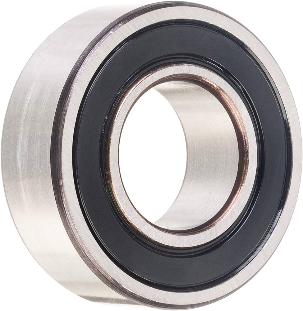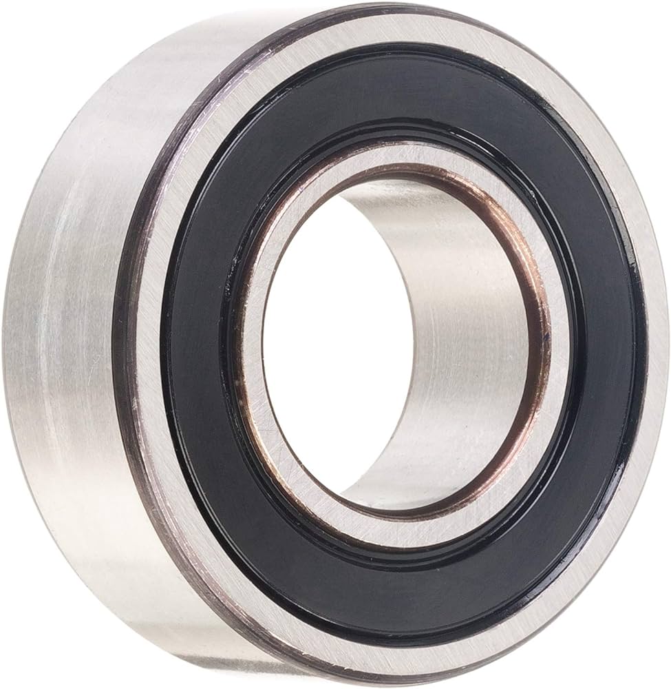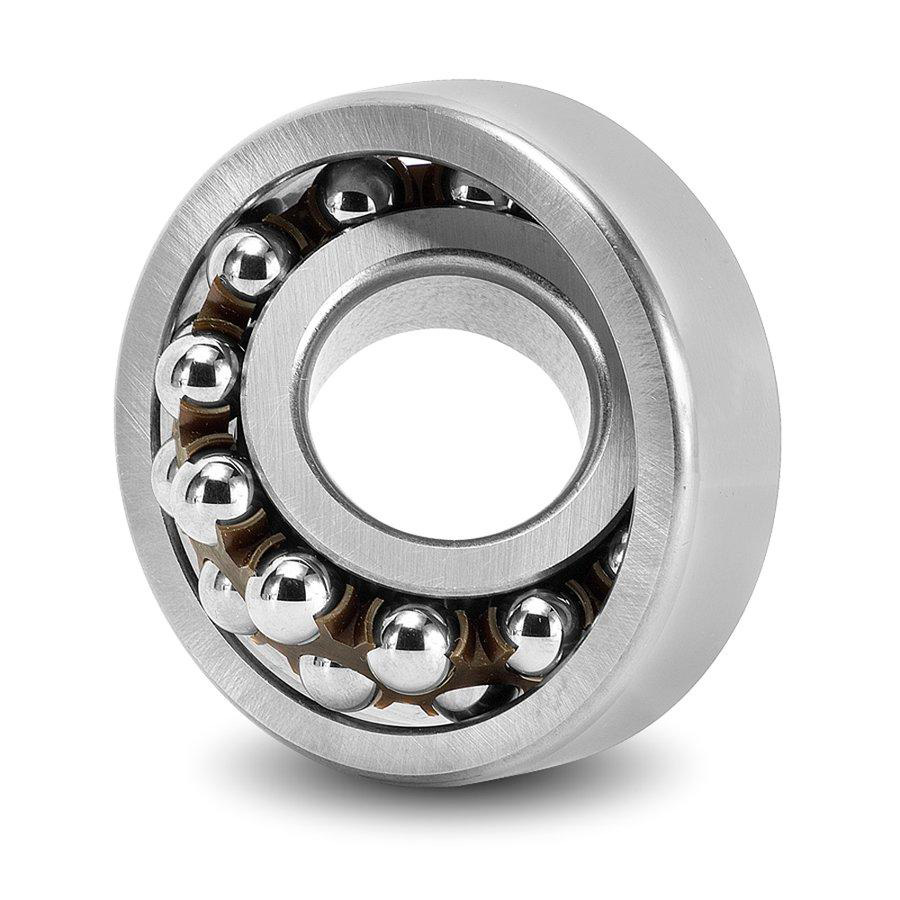


1321-KM is a self-aligning ball bearing. The configuration identifies enclosure Open and load direction Thrust. Its useful selection features are the contact arrangement, mating dimensions and actual component configuration. Read these together: a change in enclosure, clearance or material combination can matter even when two bearings share the same bore. The required reaction and the installed running condition should guide the comparison.
Contact Arrangement and Structural Reaction
1321-KM is classified in the self-aligning ball-bearing family, while its explicit load-direction entry is Thrust. Keep the supplied axial ratings and actual package geometry together when assessing the ordered configuration. General family geometry must not be used to assign an unlisted radial rating, ball-row count or numerical alignment allowance.
A self-aligning family describes an alignment-accommodation principle in general. The practical support must still agree with the actual contact members, seating interfaces and working reaction. Confirm the surrounding axial backing and any separate radial support required by the mechanism. Do not replace the stated thrust data with typical radial-bearing assumptions or use taxonomy as proof of interchangeability.
Package Dimensions and Fit Relationships
The main package dimensions are bore 105 mm, outside diameter 155 mm, and width 46 mm. Treat the shaft, housing and available axial space as a coordinated set of interfaces. Shoulder positions and clearances need to accommodate the actual bearing form without interfering with moving parts. Matching a bore alone does not establish replacement compatibility or the required installed fit. The washer-inclusive interfaces list Washer Outer Dia: 163 mm, Wahser Outer Dia Tolerance: -0.025mm to 0, Width With Washer: 49 mm, and Width With Washer Tolerance: +0.025mm to -0.3mm. They are distinct from the nominal bearing-only envelope. The bore type is Taper 1:12, which must agree with the shaft-side mounting arrangement.
Dimensional limits include bore tolerance -0.02mm to 0, outside diameter tolerance -0.025mm to 0, and width/height tolerance +0.025mm to -0.3mm. These limits describe the bearing interfaces, not a ready-made shaft or housing machining instruction. Account for which ring rotates relative to the load, the stiffness of its seat and temperature differences in service. The completed fit must preserve alignment and the intended clearance rather than merely accept assembly.
Precision and Installed Internal Condition
The internal-condition entries are radial clearance CN. Precision and clearance answer different questions: geometric control is not the amount of internal freedom between rolling elements and raceways. Preserve the stated notation without converting between ABEC, ISO or manufacturer-specific classes. An apparently similar designation should not be assumed equivalent without the applicable definition.
Installed running clearance can differ from initial clearance. Interference at a seat, a temperature difference between the rings and the load applied to the assembly can change the contact condition. Seat roundness and shoulder runout also influence alignment. Check these relationships together when judging starting torque, stiffness or heating. Neither a precision label nor a clearance code independently guarantees the accuracy of the completed mechanism.
Material Combination and Environmental Selection
The component specifications identify ring material 52100 Chrome Steel, rolling-element material 52100 Chrome Steel, and cage material Brass. Each material belongs to its own role. A ring specification does not identify the balls or cage, and a ceramic-ball entry does not make the ring ceramic. Keep the complete material pair visible when comparing contact behavior and thermal response.
Environmental selection requires the stated alloy and actual exposure conditions, not a broad bearing-family name alone. Heat treatment, surface condition, lubricant and the mating material influence the contact system. Assess the operating medium and contamination alongside the mechanical duty. Avoid extending an alloy designation into a chemical-service qualification or a universal corrosion guarantee; the ordered component combination and application conditions must support that assessment. No corrosion, electrical, chemical, food, medical, marine, or other application qualification is implied without explicit supporting data.
Interpreting Load and Operating Data
The explicit axial entries are Dynamic Thrust Load: 8665 lbf and Static Thrust Load: 71890 lbf. Keep their thrust roles; they are not radial load ratings. Dynamic and static ratings serve different checks. Rotating fatigue assessment uses the dynamic basis, whereas the static basis addresses contact deformation under stationary, peak or slowly moving loading. Neither is a permitted operating load without consideration of load combination, duty, shock and the required reliability.
Other operating entries include maximum-speed entry 2.15 under the stated ×1,000 rpm convention and temperature entry -30° to 110 °C. Keep reference conditions separate from maximum limits. Lubrication, enclosure drag, load and heat removal interact in service, so one listed operating value cannot establish the performance of the whole machine. Use the actual duty and installed condition when checking the selected bearing.
Seat Support and Assembly Control
The self-aligning function does not eliminate installation requirements. Apply fitting force through the ring being seated and keep the shaft and housing interfaces clean and controlled. Preserve the intended axial location while allowing the bearing arrangement to accommodate its normal alignment motion. A forced or distorted ring seat can undermine the useful behavior of the curved raceway.
Check the surrounding support for excessive deflection and local housing distortion. Free rotation, torque, noise and temperature observations can reveal an installation problem before sustained duty. Those checks do not replace a load assessment, but they help identify binding, contamination or lost running clearance. Shaft support and alignment should be assessed as part of the complete mechanism.
Enclosure and Lubricant Condition
1321-KM is open. Protection and lubricant retention must therefore be provided by the surrounding design. Consider how particles or process fluids could reach the rolling contacts and how lubricant is supplied during motion. Open construction can simplify access to the contact space, but it is not evidence of dry-running capability or permission to operate without contamination control.
Lubrication is specified as Required. Select the lubricant and delivery method for the application; this does not identify a grease fill already in place. Film formation and heat generation depend on speed, load, temperature and the contact materials. The lubricant must suit the enclosure and replenishment arrangement. A condition label does not set viscosity, fill quantity or a service interval; those choices must follow the complete duty and the lubricant system.
Configuration-Level Selection
1321-KM may be considered in shaft supports where angular alignment accommodation is relevant. These are general mechanical contexts, not a guarantee for a named machine or environment. Define the load direction and duty first, then compare the actual dimensions, materials, closure and internal condition. The family designation should not replace an assessment of the operating medium or the requirements placed on the contact system.
A useful comparison preserves the whole configuration. Confirm nominal geometry and tolerance, the material of each working component, the ordered enclosure and lubricant condition, and the applicable operating data. Relate those details to shaft and housing support and the required running condition. This makes differences between nearby models meaningful without assuming an unstated speed, life, precision level or environmental qualification.