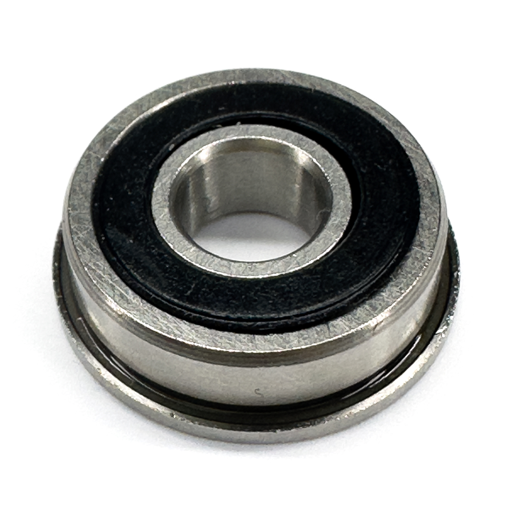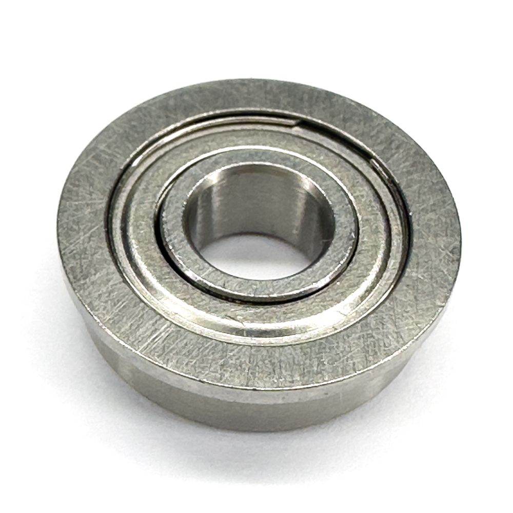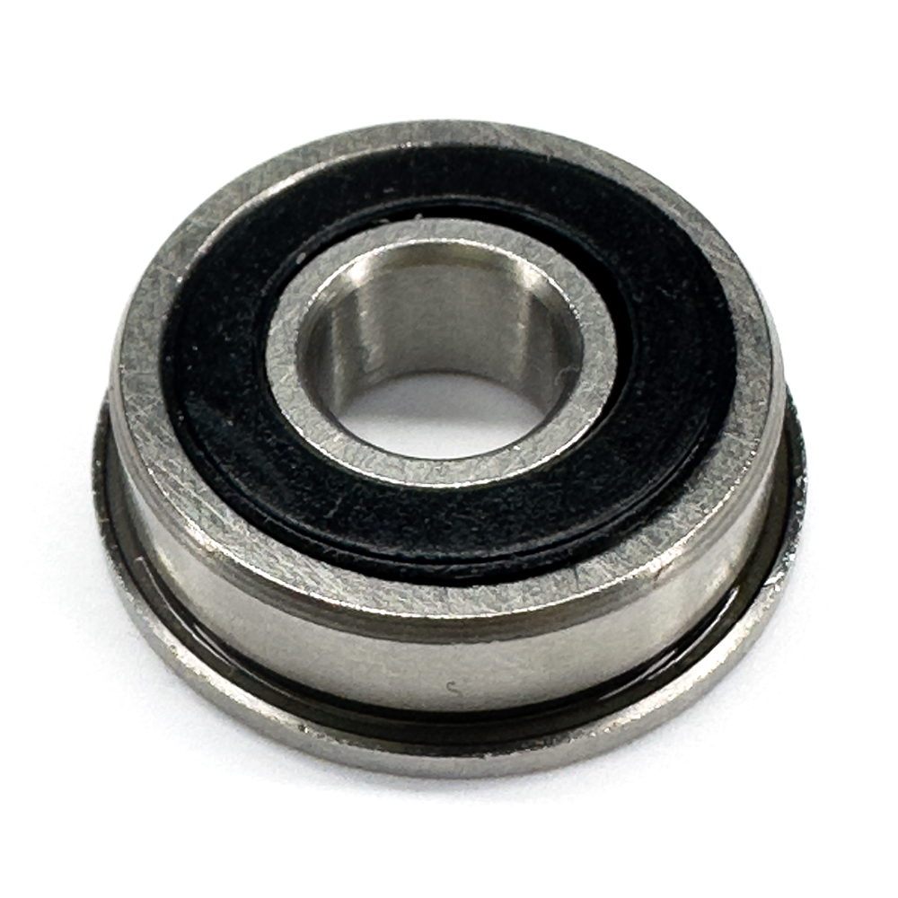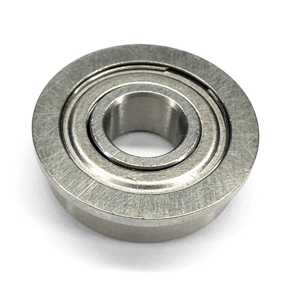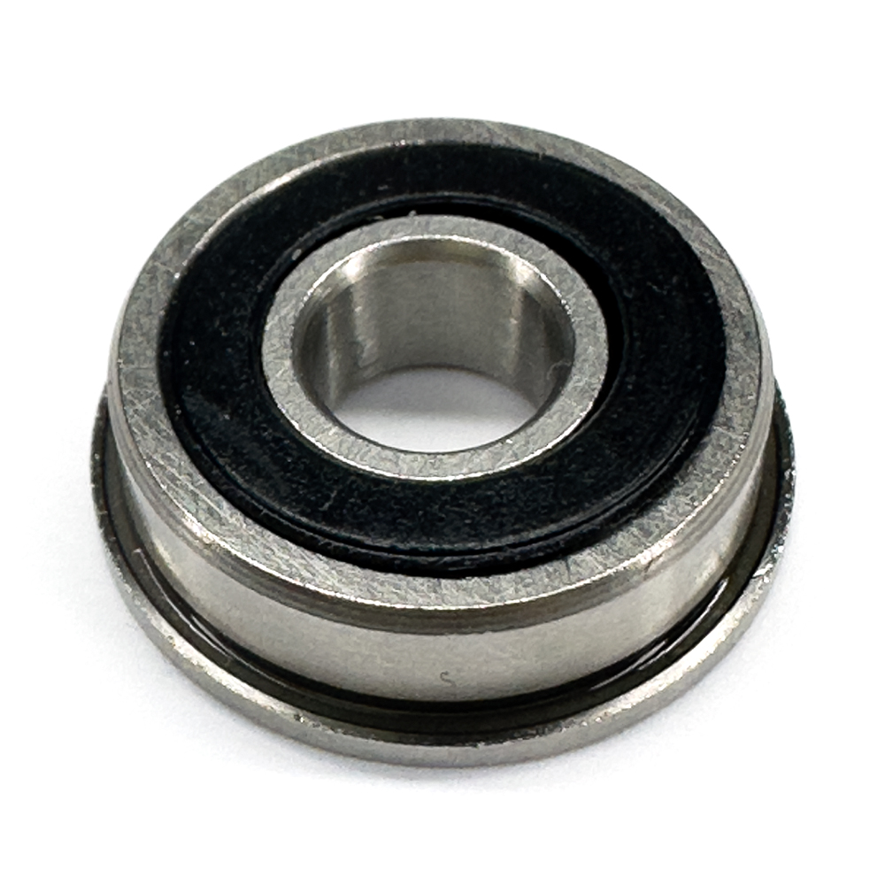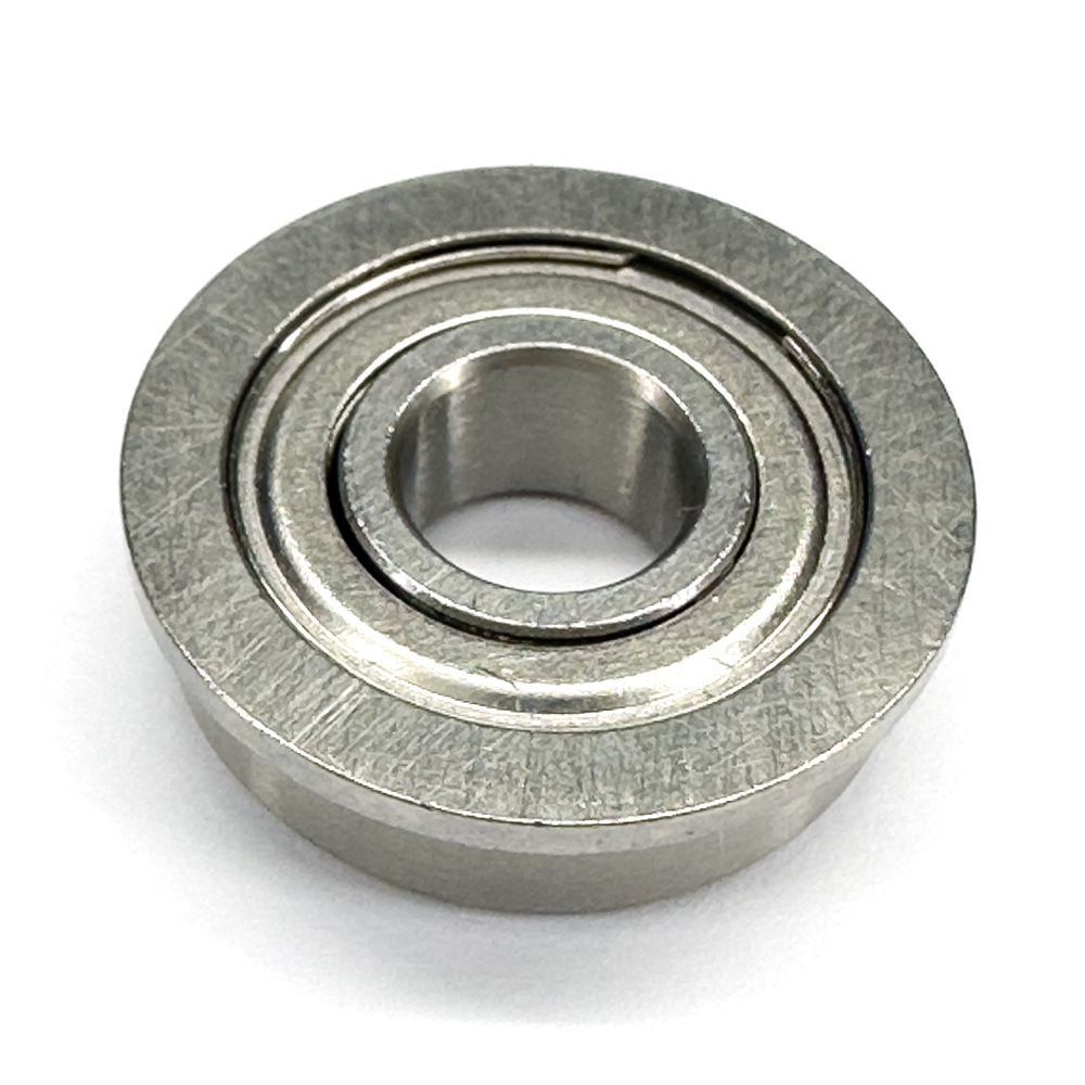


F609 is a flanged miniature ball bearing. The outer-ring flange provides a housing-side locating interface whose dimensions must be accommodated alongside the bearing envelope. The bore, outside diameter and width must work with the available installation space, while the load data and operating configuration must be assessed against the same duty conditions.
Dimensional Limits at the Interfaces
The metric dimensions of F609 include a bore of 9 mm, outside diameter of 24 mm, width of 7 mm. These dimensions locate the shaft interface, housing interface and axial envelope. All must be checked together: matching the bore alone leaves the housing diameter and axial space unresolved. The surrounding shoulders and adjacent parts must also allow the bearing to seat without interference or ring distortion.
The dimensional tolerance limits are bore: -0.008mm to 0; outside diameter: -0.008mm to 0; width: -0.12mm to 0. Keep each limit attached to its own dimension when checking the mating parts. A dimensional tolerance is not an installed clearance value. Shaft and housing sizes determine the actual fit, so their tolerances must be assessed alongside the bearing limits rather than treating every nominally matching part as equivalent.
Bearing Geometry in the Mechanism
F609 uses a single row radial ball-bearing arrangement. The balls transfer force between the inner and outer raceways, with the cage maintaining separation as they circulate. Its ball complement is 7. The radial load direction identifies the main support function. It does not establish a separate axial rating, so any combined loading needs an appropriate application check.
The compact raceway geometry makes the quality of the surrounding support important. Shaft alignment, housing concentricity and square seating faces help avoid uneven contact loading. Excessive interference or local deformation can change the internal running condition, even when the bearing itself is correctly specified. Evaluate the load path through the shaft and housing as well as through the bearing contacts.
Operating Data and Design Checks
The load data for F609 include a dynamic radial rating of 642 lbf and a static radial rating of 260 lbf. Dynamic and static ratings serve different checks. The dynamic value supports life-related evaluation under rotating load; the static value addresses contact deformation under stationary or high loading. Neither is an application allowable load by itself. Applied force, direction, shock, duty cycle and the intended reliability must be considered before deciding whether the bearing meets the design requirement.
The maximum-speed entry is 32 × 1,000 rpm. The temperature range is -30° to 110 °C. Load, lubrication, enclosure, fit and heat removal interact during operation. A speed limit should not be read as a guaranteed machine speed under every load or thermal condition. Expansion of the shaft, housing and bearing can change the internal setting, so the dimensional and thermal assessments need to address the same operating case.
Location Features and Their Mating Parts
The flange on F609 has an outside diameter of 27 mm and a thickness of 1.5 mm. It provides a housing-side axial reference, so the mating recess must accommodate both dimensions and support the locating face. Avoid seating arrangements that bend the outer ring or prevent it from resting squarely.
Keeping the Internal Setting Under Control
The precision class for F609 is ABEC1. Radial clearance is 0.002mm to 0.013mm, designated MC3. This is the supplied bearing clearance, not a calculated running clearance after fitting. Interference and temperature differences between the rings can change the internal setting. Evaluate these effects with the selected fits rather than assuming that the initial condition will remain unchanged.
Accuracy in the assembled mechanism also depends on the journals, housing seats and locating faces. Roundness, concentricity, shoulder runout and cleanliness can affect how well the bearing’s own precision is used. Controlled fitting helps avoid local deformation or unintended preload. Check the final alignment and running condition together with the bearing specification instead of relying on the precision class alone.
Keeping Material Roles Distinct
For F609, the ring material is Chrome Steel, ball material is Chrome Steel, cage material is Stainless Steel. Keep these component roles distinct when comparing alternatives. A cage material is not a raceway material, and the material of the balls cannot be used to describe every part of the bearing. The combination needs to suit the intended contact, lubrication and environmental conditions.
Material choice matters through the interaction of rolling contact, thermal expansion and lubrication. Different cage and rolling-element combinations can change mass and heat response in general, without establishing a guaranteed performance result for this assembly. Evaluate the selected combination under the intended load, speed and temperature, rather than treating the material designation as a substitute for an operating assessment.
Mating-Part Preparation and Location
During installation of F609, direct force through the ring or washer being fitted instead of through the ball contacts. Prepare clean mating surfaces and remove burrs that would prevent square seating. Select interference and assembly method with the actual support material, geometry and thermal conditions in mind. Excessive fitting force or deformation can alter the running condition before the mechanism is put into service.
For this construction, check flange seating, housing support and axial retention. Verify free rotation after assembly and investigate binding rather than assuming it will disappear during running. At miniature scale, a small particle or seating error can be significant relative to the contact geometry. Careful handling, clean support surfaces and controlled location help preserve the intended load path without prescribing an unsupported fit class or clamping value.
Enclosure Choices in Operation
The open construction of F609 leaves lubricant supply and contamination control to the surrounding assembly. Plan how lubricant will reach the rolling contacts and remain there, and how debris or process media will be kept away. Open access does not imply dry-running capability. The external protection arrangement must be compatible with the operating environment and the bearing’s mechanical support.
Lubrication for F609 is listed as required. This does not identify a factory grease fill or authorize dry operation. Select lubricant type, viscosity and delivery method with regard to load, rotational speed, temperature and enclosure. The lubricant must also be compatible with the cage and any closure materials. Replenishment and cleanliness requirements belong to the actual operating arrangement.
Bringing the Configuration Together
At family level, this construction can be considered in small rollers, instruments and rotating modules needing housing-side location. These examples do not establish compatibility with a particular machine. Selection still requires the actual loading, speed, temperature, available support and lubrication arrangement to agree with the chosen bearing configuration. Compare meaningful differences between alternatives, not just the model designation or bore size.
The selection of F609 should bring flange accommodation, housing location and the radial support arrangement into the same assessment as load, lubrication and operating conditions. A nominal size match is only one part of that decision. Confirm the configuration and mating interfaces together so that an alternative does not change the mechanical arrangement on which the design depends.