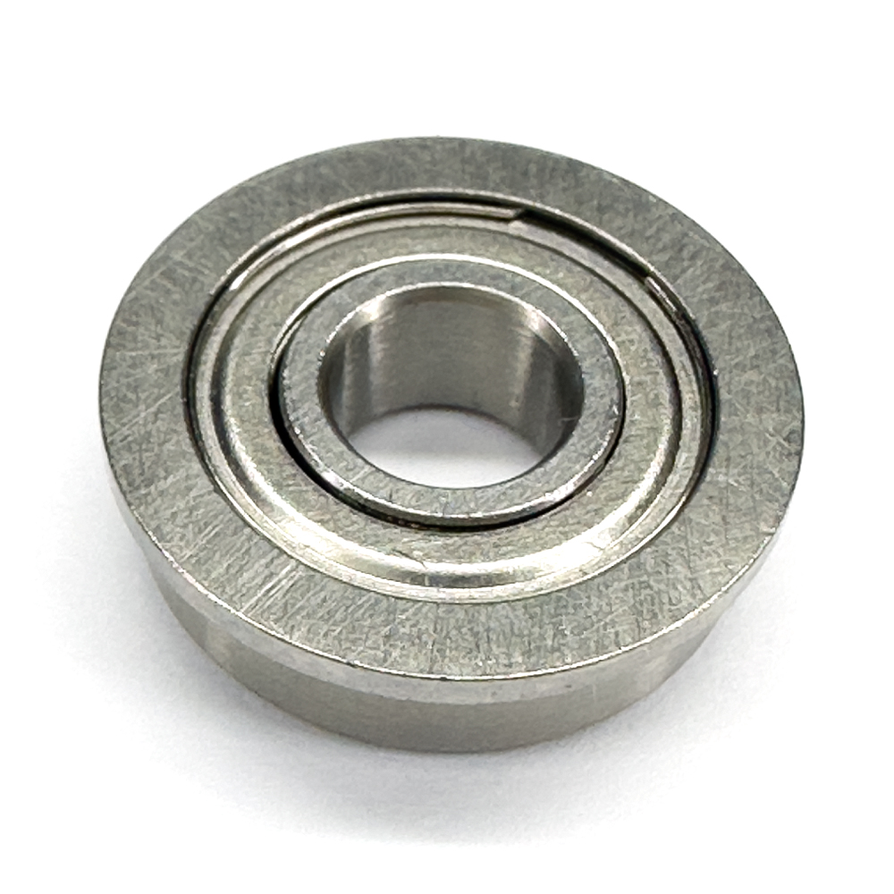
F63805ZZ Flanged Thin Section Ball Bearing
Overview |
|
| Part Number | F63805ZZ |
Characteristics |
|
| System of Measurement | Metric |
| Bearing Type | Ball |
| Ball Bearing Type | Flanged |
| For Load Direction | Radial |
| Construction | Single Row |
| Inner Ring Type | Standard |
| Seal Type | Shielded |
| Tolerance Class | ABEC-1 |
| Radial Clearance Trade No | C0 |
| Radial Clearance | 0.002mm to 0.013mm |
| Ball Qty | 15 |
Dimensions |
|
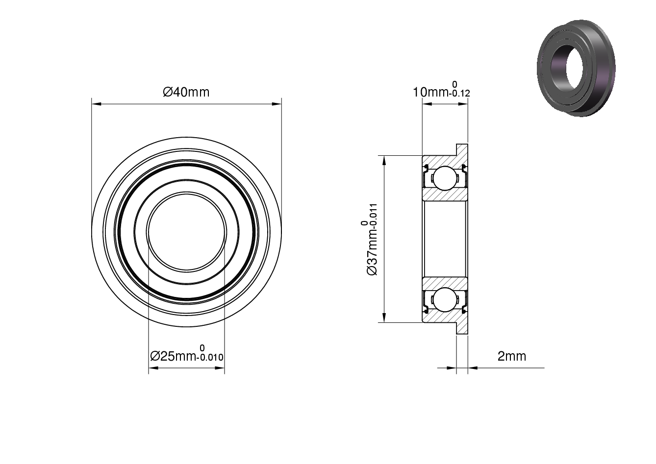
| Bore Dia | 25 mm |
| Bore Dia Tolerance | -0.010mm to 0 |
| Outer Dia | 37 mm |
| Outer Dia Tolerance | -0.011mm to 0 |
| Width | 10 mm |
| Width Tolerance | -0.12mm to 0 |
| Flange Outer Dia | 40 mm |
| Flange Thickness | 2 mm |
| Ball Dia | 3.5 mm |
Material |
|
| Ring Material | Chrome Steel |
| Ball Material | Chrome Steel |
| Cage Material | Stainless Steel |
| Shield Material | 300 Series Stainless Steel |
Performance |
|
| Dynamic Radial Load | 967 lbf |
| Static Radial Load | 659 lbf |
| Max Speed (X1000 rpm) | 18 |
| Temperature Range | -30° to 110°C |
Properties |
|
| Lubrication | Required |
| RoHS | Compliant |
| Weight | 34.1 g |
$5.25
Why Choose Bearing Maker
- Fast Global Shipping
- OEM/ODM Services
- Technical support & design
- Quality Control
- Worldwide customer base
F63805ZZ is a flanged radial thin-section ball bearing. The outer-ring flange adds a housing-side axial reference to the compact radial-bearing arrangement. The shielded construction and ABEC-1 precision class belong to the same configuration as its dimensional envelope. Selecting the bearing means considering those features together with the load path, fit and lubrication, rather than matching the model to a nominal diameter alone.
Radial Support and the Flanged Interface
F63805ZZ has a bore of 25 mm, an outside diameter of 37 mm and a width of 10 mm. This flanged radial arrangement uses the main outside diameter for radial support and the flange for housing-side axial location. The flange is not a reason to assume a different contact geometry or to assign an unsupported thrust capacity. The construction is single row. The ball complement is 15.
Treat the housing bore and its locating face as related interfaces. A tilted face can pull the thin outer ring out of its intended alignment even when the nominal diameter is correct. The radial seat should support the ring continuously; the flange should locate it without uneven edge loading.
Accommodating the Flange
The flange outside diameter of F63805ZZ is 40 mm, with a flange thickness of 2 mm. The housing opening and nearby components must accommodate that additional envelope. The locating face can establish insertion depth, but its position must be checked against the assembly’s axial stack rather than assumed from the main bearing width.
Keep the bearing square as the flange approaches the housing face. Pressing or clamping against one edge can distort the outer ring instead of seating it uniformly. A flat, correctly aligned mating face and support at the main outside diameter help preserve the intended contact condition; the locating feature cannot compensate for an inaccurate radial seat.
Clearance, Precision and Fit Are Different Checks
The radial-clearance entry for F63805ZZ is 0.002mm to 0.013mm. Its designation is C0. This is not the same quantity as its ABEC-1 precision class. Clearance concerns the internal space between the rolling contacts; precision classification concerns dimensional and running accuracy. Neither value alone establishes the installed preload or the accuracy of the complete mechanism. Fits and temperature differences can alter the running contact condition after assembly.
The interface tolerance limits are bore: -0.010mm to 0; outside diameter: -0.011mm to 0; width: -0.12mm to 0. Keep the unit and dimensional role of each limit intact. These bearing tolerances do not prescribe the finished shaft or housing size. Assess interference, thermal growth and shoulder alignment together: excessive fit-induced ring deformation can consume clearance or introduce uneven loading, while inadequate location can allow unwanted movement. Thin rings make the surrounding part geometry especially consequential.
The Material Combination at Each Component
The component materials for F63805ZZ are rings: Chrome Steel; balls: Chrome Steel; cage: Stainless Steel. Rings and balls form the loaded rolling contacts, whereas the cage separates and guides the balls. Those roles should remain distinct when comparing configurations: the cage material does not identify the rings, and a ring material does not identify the rolling-element material.
Material choice affects contact behavior, thermal response and the way the cage operates within the bearing. Stainless steel is present in the specified component combination, but that does not establish resistance to every fluid or atmosphere. Exposure must be assessed for each relevant component and for the lubricant. Contamination, surface condition and operating temperature remain part of the application assessment. A material label cannot replace a review of the rolling contacts and the surrounding enclosure.
Enclosure and Lubrication as One Arrangement
Shields provide a non-contact barrier around the bearing space. They help retain lubricant and reduce direct entry of larger particles without functioning in the same way as contact seals. A shielded bearing should not be selected on the assumption that it excludes liquids under all conditions. The surrounding enclosure still determines the exposure of the rolling contacts. The shield material is 300 Series Stainless Steel.
Lubrication is required. Establish lubricant type, supply and quantity for the real duty rather than assuming a particular factory fill. Load, speed, temperature and orientation affect film formation and heat. Too much lubricant can increase churning, while an inadequate film can impair contact behavior. Any replenishment provision must maintain cleanliness and avoid damaging the closure or forcing the slender rings out of alignment.
Interpreting Ratings without Mixing Load Roles
For F63805ZZ, the dynamic radial load rating is 967 lbf and the static radial load rating is 659 lbf. Dynamic and static ratings answer different questions: fatigue assessment during rotation and the risk of permanent deformation under stationary, peak or slowly moving load. They are not interchangeable operating limits.
The temperature-range entry is -30° to 110°C. Maximum speed is 18 in the stated ×1,000 rpm convention. Retain that multiplier when interpreting the value. These figures have to be considered with the selected lubricant, closure, fit and heat-removal conditions. A demanding load case can change the practical operating condition even when one isolated value appears acceptable. Calculate the bearing reactions from the complete mechanism and use the real duty cycle; the ratings do not establish a particular service life or assembled-system performance.
Mounting without Distorting the Rings
Mounting F63805ZZ begins with clean, burr-free seats and a review of the complete bearing envelope. Seat the radial interface squarely, then check that the flange meets its locating face uniformly rather than being forced into position at one edge. Installation force for an interference fit should act on the ring being fitted, avoiding a force path through the balls and raceways. Shoulder and adjacent-part geometry must allow the bearing to seat without unintended contact or uneven axial loading.
The assembly should be checked after clamping as well as before it. Housing deformation, tilted shoulders or uneven restraint can change the running clearance and load distribution. Free rotation and observations of torque, noise and temperature can help identify binding before normal service. Those checks complement dimensional inspection; they do not replace an assessment of alignment, lubrication and the loads that the assembled mechanism will actually impose.
Choosing the Complete Configuration
This bearing type is commonly considered for compact mechanisms where a housing-side locating face is useful alongside radial support. Use that context to frame the engineering assessment, not as a guarantee that a particular machine is suitable. The load directions, duty cycle, operating speed, exposure and available support stiffness still have to be established. A replacement with the same bore can differ in contact geometry, closure or internal condition, so nominal size alone is not sufficient.
For F63805ZZ, start with the radial seat, flange geometry and the axial locating stack, then assess the shielded configuration and ABEC-1 precision class against the same operating conditions. Materials, lubrication and the selected fits interact with those choices. Keeping the configuration intact through purchasing and assembly is more useful than evaluating each parameter in isolation: the bearing must work with the shaft, housing and reaction path as one mechanical arrangement.
Related products
-
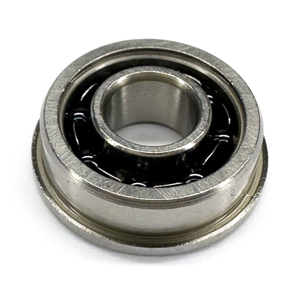
F6908 Flanged Thin Section Ball Bearing
-
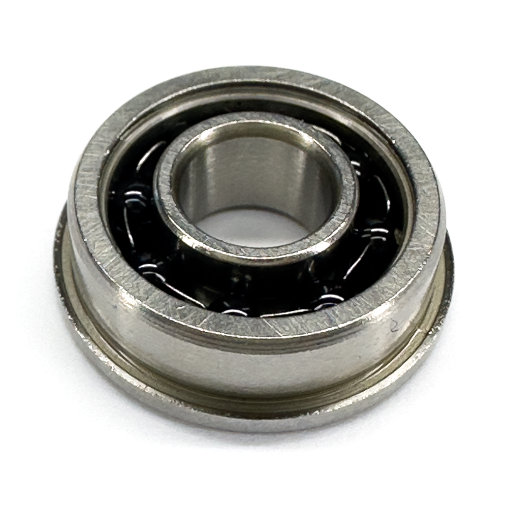
F6910 Flanged Thin Section Ball Bearing
-
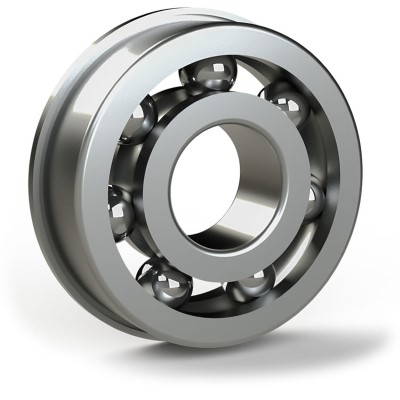
SF6808 Flanged Thin Section Ball Bearing
-
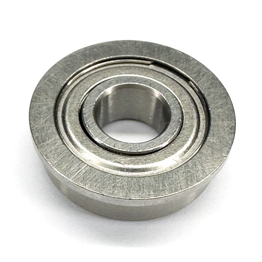
SF6809ZZ Flanged Thin Section Ball Bearing
-
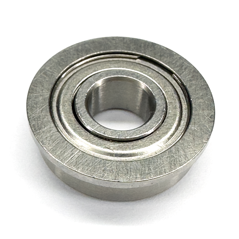
SF6909ZZ Flanged Thin Section Ball Bearing
-

F6808 Flanged Thin Section Ball Bearing
-
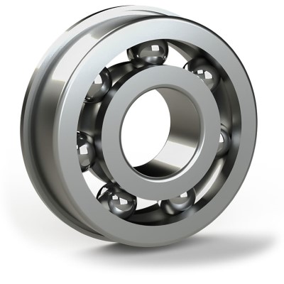
SF6810 Flanged Thin Section Ball Bearing
-
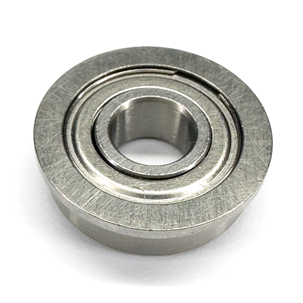
F6909ZZ Flanged Thin Section Ball Bearing