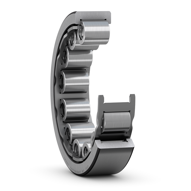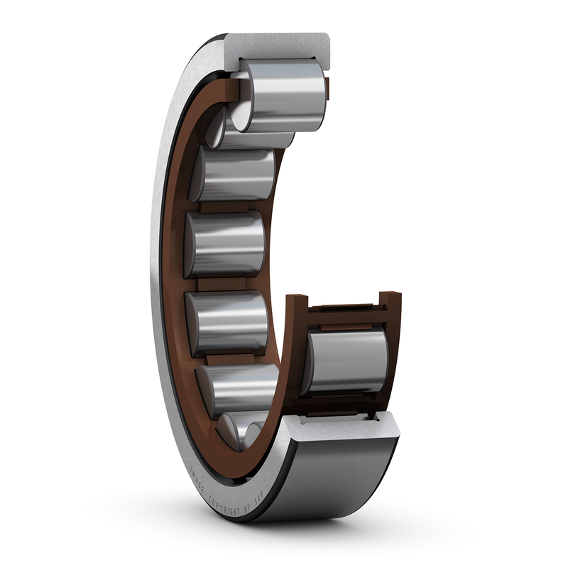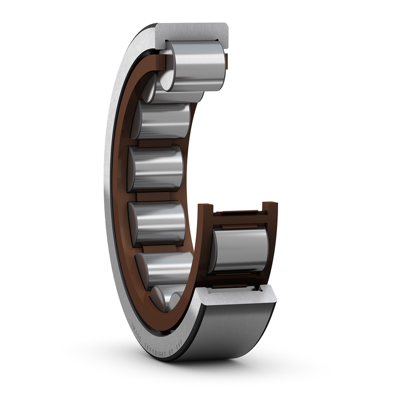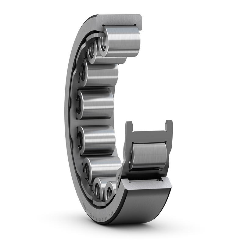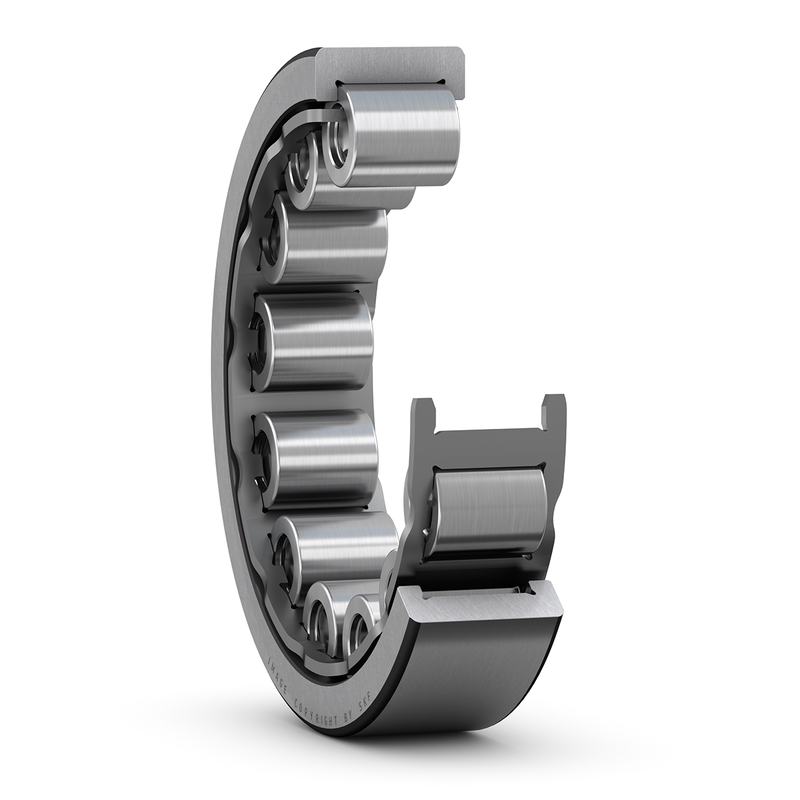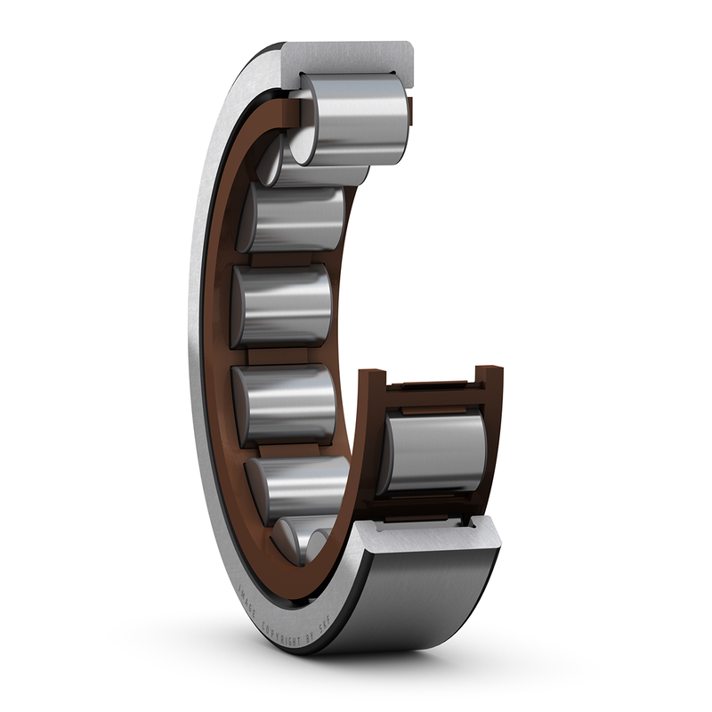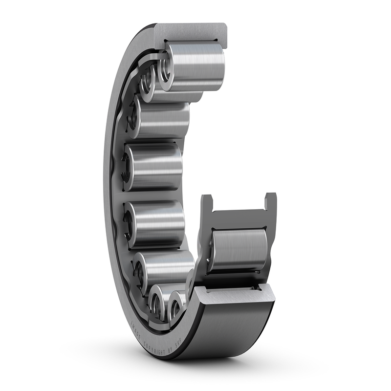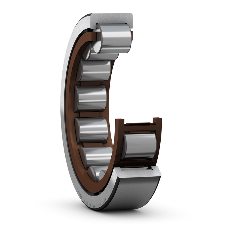
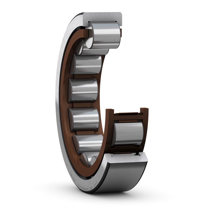
RNU 2304 ECP is a cylindrical roller-bearing assembly supplied without an inner ring. Its configuration identifies bearing type Cylindrical, construction Single Row, load direction Combined, and enclosure Open. The shaft or a separately engineered inner raceway completes the contact system; the supplied part must not be specified as a complete bearing with both rings. Nominal size is only one part of that decision. Relate the required reaction to the available installation space, the working component materials and the lubricant arrangement before treating another model as an alternative.
Roller Geometry and the Working Reaction
RNU 2304 ECP is supplied without an inner ring. Its cylindrical rollers operate against a shaft raceway or another separately specified inner contact member. That interface is part of the bearing geometry, not simply a mounting journal inside a supplied inner ring. The under-roller diameter and the mating surface assessment therefore deserve particular attention when evaluating this incomplete assembly.
The mating raceway needs suitable geometry and surface condition for rolling contact. Confirm the required hardness, finish, dimensional tolerance and alignment through the applicable design requirements; those values cannot be assigned from the omission of an inner ring. Outer support and axial retention must also suit the supplied arrangement. Do not attribute the performance of a fully assembled alternative to this part without a complete contact-system assessment. The distinct configuration entries are inner-ring provision Without. Preserve each entry in its stated role.
Mating Dimensions and Package Relationships
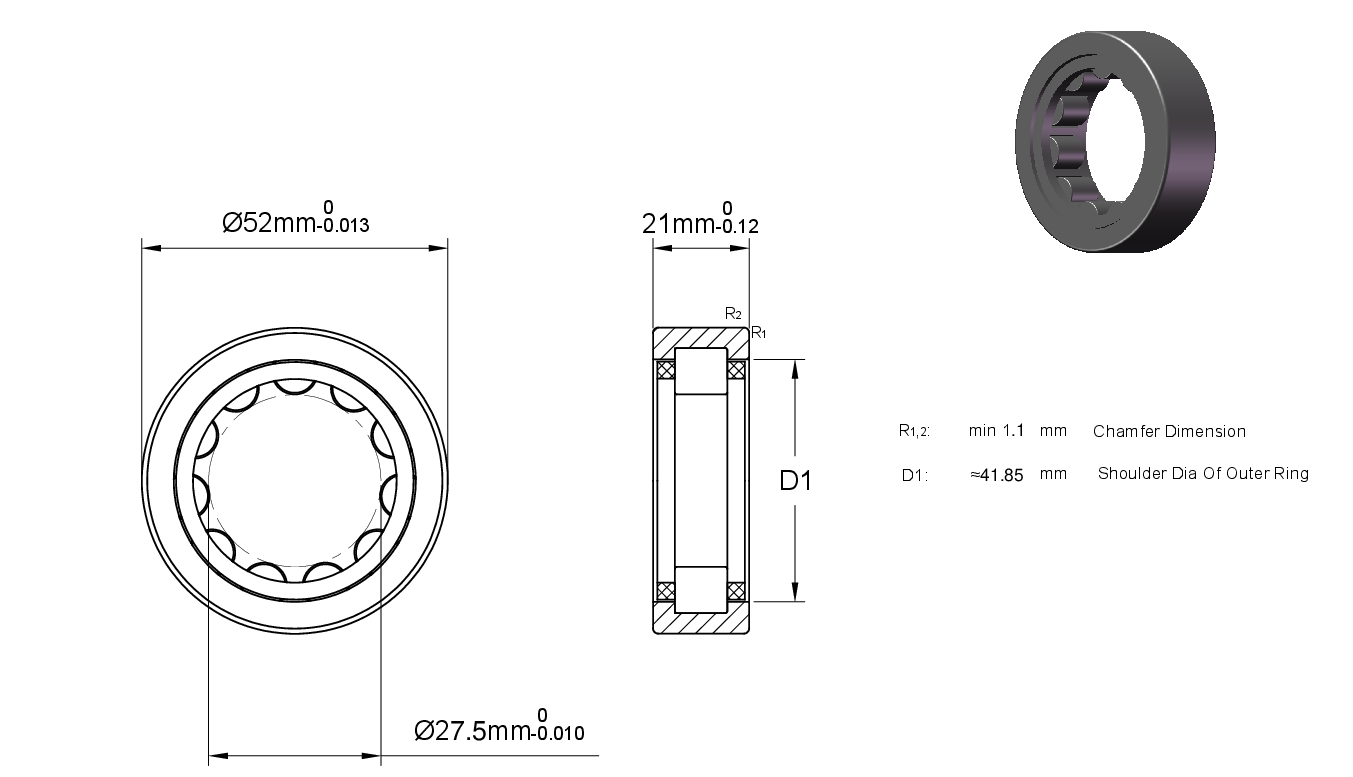
The main dimensional interfaces identify outside diameter 52 mm, width 21 mm, and diameter under rollers 27.5 mm. The measurement system is Metric. Coordinate shaft location, housing seating and available axial space using those separate roles. A raceway diameter is not automatically a mounting bore, and a washer or cup width is not necessarily the total package width. Nominal size agreement alone does not prove that an alternative will fit and function correctly.
The stated dimensional limits include outside diameter tolerance -0.013mm to 0, width/height tolerance -0.12mm to 0, and Diameter Under Rollers Tolerance: -0.01mm to 0. These are interface limits, not a ready-made machining instruction for a shaft or housing. Consider which member rotates relative to the load, the stiffness of its seat and thermal changes during operation. The installed fit must preserve ring shape and the intended contact condition as well as permit assembly.
Component Materials and Contact Pairing
The component material entries specify rings as Chrome Steel, rolling elements as Chrome Steel, and cage as PA66 cage, roller centred. Each entry belongs to the component named, not to an assumed homogeneous bearing. Keep roller or needle material separate from the rings, cage and any springs. Their combination determines the contact pair and the surrounding mechanical interfaces; a retainer material alone says nothing about the raceway alloy.
Material selection must be related to the actual exposure and operating duty. Surface condition, heat treatment and the mating material affect rolling contact, while lubricant compatibility matters throughout the contact system. Assess contaminants and temperature with the stated component combination. An alloy or material label does not by itself establish chemical-service qualification, corrosion immunity or a guaranteed service life for the installed mechanism.
Geometric Control and Installed Contact Condition
Confirm the required initial internal condition and geometric control for the ordered arrangement. Precision, clearance and preload describe different aspects of a rolling assembly. Preserve the notation as stated without converting between standards or treating a clearance code as an accuracy class. The installed behavior depends on the contact geometry as well as the specified component limits.
Without a supplied inner ring, the mating raceway is part of the internal-condition assessment. Its geometry, surface finish and operating temperature affect the running contact relationship. Confirm the complete installed clearance with the outer support and mating member. A dimensional tolerance on the supplied part is not a guarantee of the accuracy or clearance of a completed bearing arrangement.
Support Interfaces and Assembly Assessment
Treat the shaft raceway as a working bearing surface, not merely a location for an absent inner ring. Its diameter, geometry and surface condition must agree with the supplied roller assembly. Avoid assigning an arbitrary hardness or finish value. The outer seat should maintain alignment and ring shape under the installed fit and operating reaction.
Check axial retention and lubricant access as part of the complete contact arrangement. Assembly force should act through the supported member instead of damaging the rolling contacts. Inspect the installed motion and the mating raceway condition before accepting the arrangement. The component identity does not establish a ready-made replacement for a complete bearing with the same nominal size.
Ratings and Their Operating Basis
Applicable operating entries include dynamic radial rating 10688 lbf and static radial rating 8550 lbf. Dynamic and static ratings serve different checks: fatigue assessment and contact deformation are not interchangeable. Neither figure alone is a permitted working load. Account for load combination, shock and the required reliability, preserving any speed, revolution or row-specific basis attached to a rating.
The operating limits list Max Speed (X1000 rpm): 18 and Temperature Range: -30° to 110 °C. Keep every qualifier and unit attached to its own value. A limiting speed, a reference speed and a lubricant-specific speed describe different conditions; none establishes a universal running speed. Check heat release, lubricant delivery and the surrounding support against the actual duty before setting an operating point.
Contact Protection and Lubricant Supply
The open enclosure leaves contamination control and lubricant retention to the surrounding design. Determine how particles, fluids or debris might enter the working contact space and how lubricant reaches it during motion. Open construction is not evidence that lubrication can be omitted or that the assembly is protected against the operating environment.
The lubrication condition is Grease, Oil. Keep that condition when assessing the ordered arrangement. Film formation and heating depend on the contact materials, speed, load and temperature. Match viscosity and delivery to the complete duty, including startup and replenishment conditions. A general lubricant condition does not set a fill quantity, a service interval or a permissible operating temperature by itself.
Selection of the Complete Configuration
RNU 2304 ECP may be considered in compact shaft supports in which the mating inner raceway is deliberately engineered. This is general engineering context, not suitability approval for a named machine. Establish the load direction and duty first, then compare the contact arrangement, mating dimensions and actual internal condition. The surrounding design must support the intended reaction without an incompatible fit or an unstated operating capability.
A useful specification keeps the exact model and working component combination visible. Compare enclosure and lubricant requirements, material roles, dimensional limits and ratings on their stated bases. Relate those facts to seat support, thermal change and the completed running condition. A shared size or series designation alone does not establish interchangeability, guaranteed life or the performance of the installed mechanism.