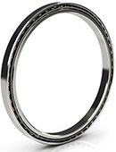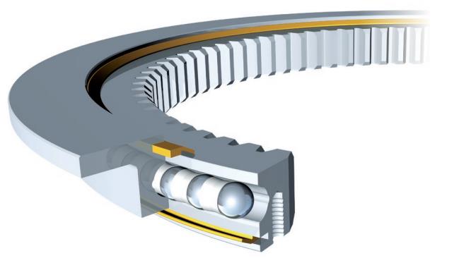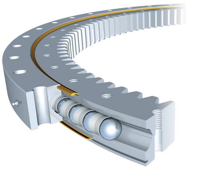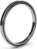

VI140326-V is a four-point contact ball slewing ring. The configuration identifies Bearing Type: Standard and Series: V Series. It provides a rotating joint between supported structures. The contact arrangement, the ring mounting interfaces and the drive connection must be selected together, rather than treating the outside envelope as the complete specification.
Contact Arrangement and the Supported Joint
VI140326-V identifies Type: Ball. Four-point ball contact gives the joint distinct contact paths for reacting changes in load direction. Axial reaction, radial reaction and overturning effects must be assessed together; a general description of the geometry is not a permissible combined-load envelope.
Contact angle, ring deflection and the installed internal freedom affect which contacts carry reaction at a given instant. The supporting structure and bolt system therefore belong in the same assessment as the bearing ratings.
Drive Interface and Gear Geometry
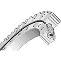
VI140326-V identifies internal gear. The mating drive works at the inward-facing tooth interface; its space and alignment must be coordinated with the inner envelope and the moving members. The mesh geometry identifies Pitch Diameter Of Gear: 10.059″, Diametral Pitch: 3.5, and Number Of Gear Teeth: 73. Pitch diameter and tooth count describe the mesh, not the bearing mounting diameter or a permissible rotation speed.
The tooth details identify Width Gearing: 1.575″. Tooth geometry, flank contact and backlash must agree with the mating drive. A tooth-force entry is not an overall torque guarantee. Support deflection can change the mesh, so the bearing seating and the gear alignment need to be checked together.
Envelope and Individual Ring Interfaces
The main envelope of VI140326-V identifies Inside Diameter Of Inner Ring: 9.843″, Outside Diameter Of Outer Ring: 15.039″, and Height Of Overall Bearing Assembly: 2.323″. The inner opening, outer envelope and axial package serve different layout checks. None should be substituted for a mounting-hole circle or gear pitch diameter. Allow room for adjacent members over the full intended motion, not only in one static position.
Ring-specific geometry identifies External Diameter On Inner Ring: 12.598″, Internal Diameter On Inner Ring: 13.11″, Height Of Inner Ring: 1.339″, and Height Of Outer Ring: 2.087″. Ring heights and raceway diameter have their own roles and are not interchangeable with overall assembly height or an opening diameter. Check axial overlap and radial clearance against the actual interfaces. Preserve the stated units for each dimension rather than converting a measurement-system label into a unit for another value.
Attachment Patterns and Installed Geometry
The inner-ring attachment identifies Bolt Circle In Inner Ring: 11.417″, Number Holes In Inner Ring: 8, and Size Holes In Inner Ring: 0.433″. The outer-ring attachment identifies Bolt Circle In Outer Ring: 14.252″, Number Holes In Outer Ring: 8, and Size Holes In Outer Ring: M10. The two ring attachment interfaces are separate connections. Match each stated circle, quantity and hole form to its own supporting member; do not exchange inner and outer patterns because the nominal bearing size agrees.
Establish the required seating and installed running condition with the joint design. Tolerance, clearance and runout describe different checks. Flat backing, fastener load and structural stiffness influence installed geometry; a nominal dimension does not establish a bolt torque or an assembled preload. Confirm seating and alignment before applying normal duty.
Rating Direction and the Combined Duty
Axial entries for VI140326-V identify Basic Dynamic Load Rating(Ca): 18450 lbs and Basic Static Load Rating(C0a): 88875 lbs. The distinct radial entries identify Basic Dynamic Load Rating(Cr): 16650 lbs and Basic Static Load Rating(C0r): 35550 lbs. Keep dynamic and static bases separate when checking the duty. Where more than one rating notation is given, retain each notation rather than treating the values as interchangeable or assigning a new rating basis.
An overturning requirement needs the applicable moment assessment as well as the force assessment. The separately stated tooth-force entries are Max Gear Tooth Load Fz: 3622.5 lbs and Permissible Tooth Forces T: 2430 lbs. Joint loads must be checked with support deflection and the fastener system. Separate maximum values do not prove simultaneous capacity, fatigue life or a speed limit. Tooth forces and bearing reactions belong to different checks; neither can be converted into an unlisted whole-joint torque rating.
Separate Material Roles
Material roles remain separate in VI140326-V. The ring-material entry is 42CRO or 50MN. The ball-material entry is Chrome Steel. These names describe their individual members, not a uniform whole-bearing material. Any alternatives joined by “or” remain alternatives; confirm the ordered member configuration rather than assuming that every listed material is fitted.
The cage-material entry is Nylon or 300 Series Stainless Steel. The seal-material entry is NBR. Cage guidance and seal material have different functions from ring contact support. Material names alone do not establish corrosion qualification, heat treatment, temperature limits or lubricant compatibility. Consider the actual operating medium and the individual member condition without assigning an unlisted environmental capability.
Lubricant Access and Handling
Lubrication and contamination control must suit the working contacts and the installed position of VI140326-V. Plan lubricant access through the actual assembly design; no fitting quantity or replenishment interval follows from the bearing designation. A seal-material name is not an ingress-protection rating. Lubricant compatibility and contamination control must be assessed for the installed environment.
The stated weight is 18 Kg. Handling and seating should preserve the ring faces and working geometry. Use the applicable lifting and mounting procedure, without assigning lifting points or tooling from the bearing name. Mounting forces should act through the member being seated rather than across rolling contacts. After installation, check motion, alignment and lubricant access before introducing the intended load.
Putting the Joint Specification Together
Select VI140326-V as a four-point contact ball slewing ring with internal gear. The decision should connect contact geometry, the two ring interfaces, the mounting support and the applicable load case. Compare the exact tooth and attachment data when considering a replacement; an equal outside diameter or similar family name cannot prove interchangeability.
Before release, retain the exact designation with the ring dimensions, distinct rating bases and ordered material configuration. Verify the mating design, fastening assessment, gear mesh where present and installed running condition. These checks establish a coherent rotating-joint specification without turning general engineering function into approval for a particular machine or operating environment.