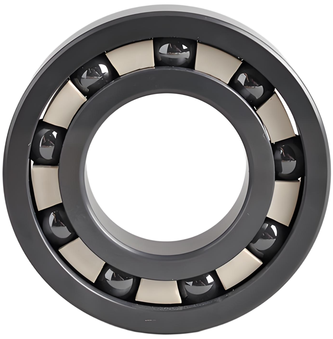
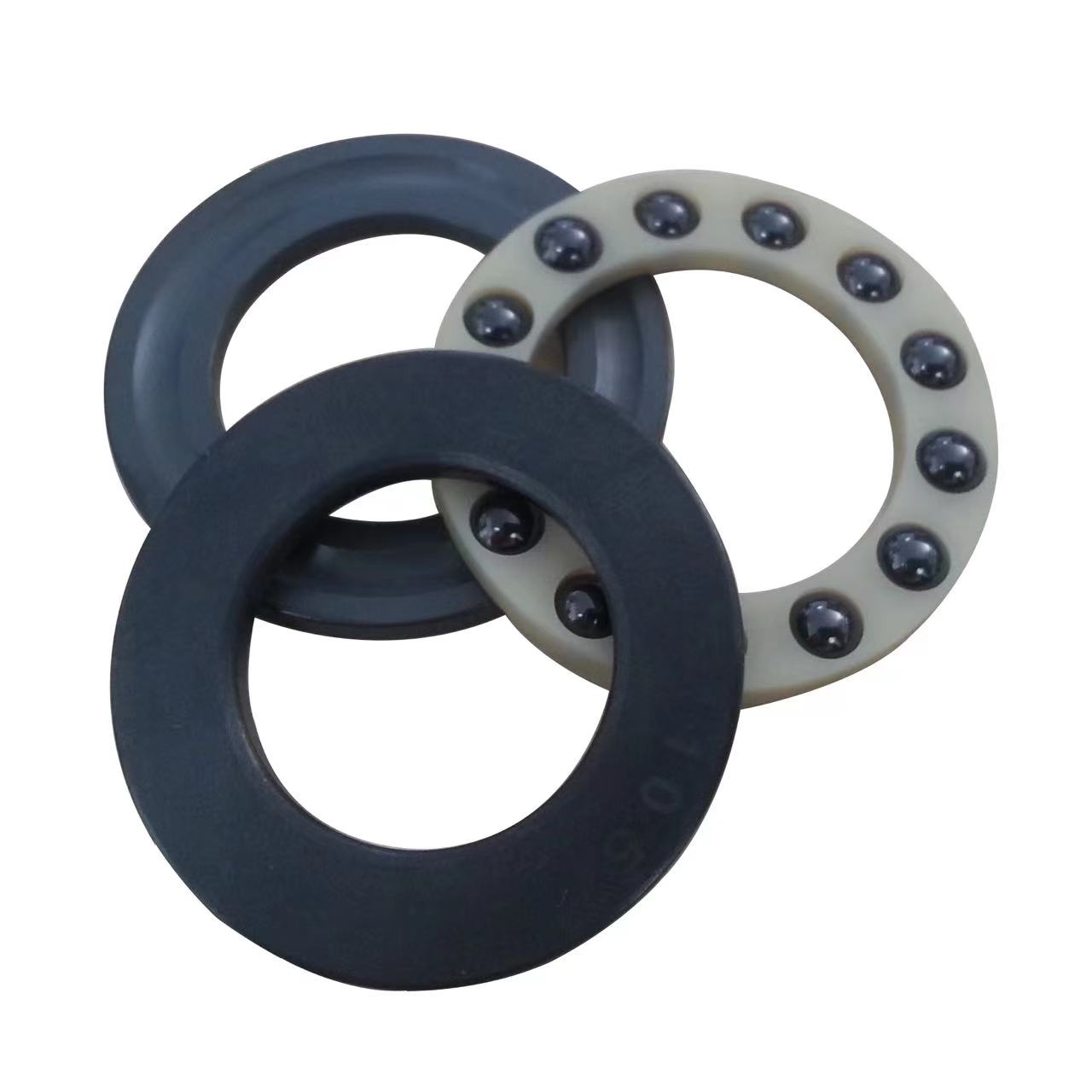
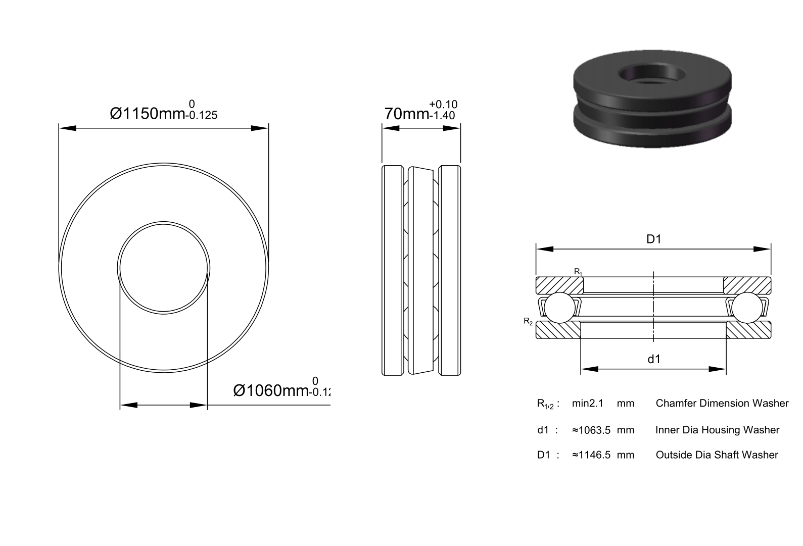
CE510/1060 MSC is a full-ceramic thrust ball bearing. Axial reaction and washer support define the main selection questions for this construction. Its dimensional envelope is bore 1060 mm, outside diameter 1150 mm, and width 70 mm. Consider these features as parts of the installed contact system, together with component materials and the actual duty, rather than treating the ceramic designation as a performance rating.
Supporting the Axial Reaction
The thrust-ball load path runs through shaft washer, ball contacts and housing washer. The seating faces must carry that reaction squarely. Uneven backing changes contact around the circumference and can load the washers locally even when the nominal axial force is acceptable. The construction entry for CE510/1060 MSC is Single Direction. Its stated load direction is Thrust.
The direction of thrust must agree with the stated construction. A double-direction arrangement is not interchangeable with a single-direction arrangement merely because their bores match. Provide radial guidance elsewhere when the machine requires it, and check how the shaft is located during reversal or unloading.
Choosing the Component Combination
The rings material is Silicon Carbide. The rolling elements material is silicon carbide (SiC). The cage material is PEEK. Keep each material tied to its own part. A rolling-element compound does not identify the rings, and the cage remains a separate choice with its own guidance and lubricant-compatibility requirements.
Full-ceramic construction concerns rings and rolling elements. It does not make the cage ceramic or make different ceramic compounds equivalent. Compare the actual contact pair, support materials and temperature gradients. Density, elastic response and thermal expansion influence the operating condition, but a ceramic name alone cannot establish chemical compatibility, electrical isolation or an allowable duty.
Interpreting the Operating Data
The load data for CE510/1060 MSC include dynamic axial rating 25718 lbf and static axial rating 263026 lbf. Dynamic and static ratings are not alternative labels for the same operating limit. Dynamic data support a rolling-load life assessment; static data address the risk of lasting contact deformation. Resolve the forces at the bearing and apply the appropriate calculation before comparing the machine duty with either value.
The speed entry is 0.42 × 1,000 rpm. The temperature-range entry is -176 to 2192 °F. Use these entries with the applicable enclosure, cage and lubrication conditions. A reference speed is not automatically a limiting speed, and a broad temperature entry does not establish continuous operation at every speed or load across that range. Heat generated at the contacts and removed through the surrounding structure must also be considered.
Enclosure and the Lubricated Contact
Establish the enclosure arrangement for CE510/1060 MSC before choosing contamination control. Check the exact barrier arrangement without adding a seal or shield that is not specified.
The family designation does not identify a lubricant. Select lubricant type and quantity for the contact pair, cage, enclosure and duty. Changing a grease or an oil supply can change drag, replenishment and heat removal even when the dimensional fit remains the same.
Assembly Accuracy and Internal Freedom
Plan the assembly force through the part being fitted. Passing a press force through the rolling contacts risks local damage rather than seating the ring cleanly. Square shoulders, clean seats and controlled support around the circumference help retain the intended geometry. Clamping should locate the bearing without forcing a distorted seat into the rings.
Precision, initial clearance and installed preload describe different aspects of the assembly. Interference and temperature differences can alter the running internal condition. Check shaft and housing fits, seat form and shoulder runout together; a close dimensional match cannot establish the accuracy of the complete rotating system.
Mating Surfaces and the Duty Cycle
The mating-interface details include bore dia tolerance: -0.125mm to 0, outer dia tolerance: -0.125mm to 0, and width tolerance: +0.1mm to -1.4mm. A fillet that interferes with a ring corner prevents full seating, while an inadequate abutment can leave the load-carrying face poorly supported. These dimensions concern distinct surfaces and must not be substituted for the main bore, outside diameter or width.
For CE510/1060 MSC, assess starts, steady rotation, load changes and stops as parts of the same duty. The governing load case may not occur at the highest speed. Thermal growth can also shift the load between supports, so verify the locating arrangement, remaining clearance and lubricant supply over the operating cycle rather than at one nominal condition.
Matching the Bearing to the Support Arrangement
Choose CE510/1060 MSC by matching its contact geometry and actual component configuration to the support arrangement. Verify the primary dimensions first, then orientation or axial location, load direction, enclosure and lubrication. Use the explicit ratings and precision or clearance entries where provided. Missing values need confirmation, not substitution from another ceramic product.
The important application question is where the axial reaction is supported and how washer seating is maintained under load. The bearing family describes a useful construction choice. Acceptance for a particular machine still depends on the complete duty calculation and installation, not a general promise attached to its material name.