
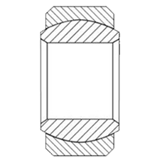
AW3V is an aerospace spherical bearing. Its selection connects spherical contact with the ball and race widths, the available angular movement and the surrounding shaft and housing interfaces. The measurement-system entry is Inch; individual dimensional values retain their stated units. The exact designation identifies the configuration to compare, while the geometry and operating data determine the engineering checks needed for the intended joint.
Spherical Contact and Angular Accommodation
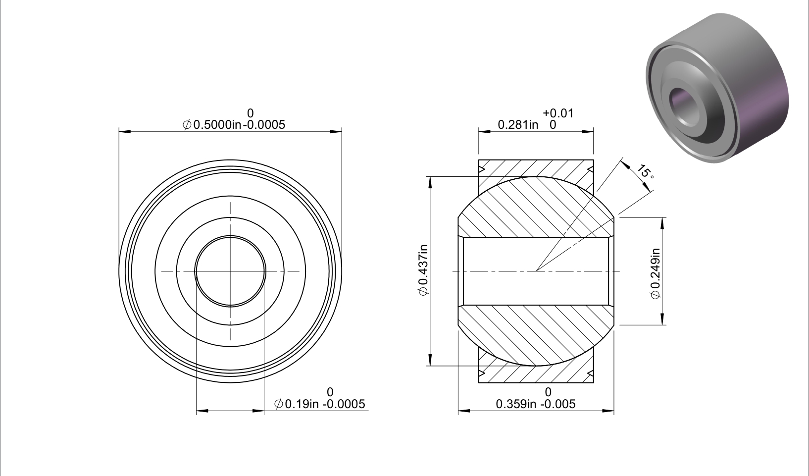
AW3V identifies ball diameter: 0.437″. The spherical relationship permits relative angular accommodation while transmitting reaction through the contact. This ball is the articulating member of the spherical bearing; it is not a complement of rolling balls. Keep that distinction when comparing motion, contact condition and support requirements.
Angular movement changes the relationship between the bearing and adjacent members. Available space around the ball and race, the actual load direction and the retained contact area must be considered together. Do not evaluate a spherical joint only at its central position: the surrounding shaft, spacers and support can restrict the usable movement even when the bearing itself has an angular-motion entry.
Envelope, Widths and Mating Interfaces
The envelope of AW3V identifies bore diameter: 0.19″, outer diameter: 0.5″, ball width: 0.359″, and race width: 0.281″. The bore locates the shaft interface, the outside dimension locates the housing interface and the individual widths define the axial package. An overall fit check therefore needs more than a single diameter. Width differences affect the space available for surrounding members and should remain associated with the ring, ball or race named in the dimension.
The additional interfaces identify shoulder diameter: 0.249″. A shoulder, flange or ball-flat dimension has a different role from the main opening or outside envelope. Check axial seating, edge clearance and the surrounding motion against the applicable dimensional definition. A feature diameter should not be substituted for another interface simply because the numerical values are close.
Dimensional Limits and the Installed Fit
The dimensional limits identify bore-diameter tolerance: -0.0005″ to 0″, outer-diameter tolerance: -0.0005″ to 0″, ball-width tolerance: -0.005″ to 0″, and race-width tolerance: -0.005″ to 0″. Tolerance entries belong to their named dimensions. Diameter limits control a different interface from width limits, and a tolerance range should not be interpreted as an internal clearance or a running-accuracy class. Retain signs, endpoints and units when checking the mating shaft and housing dimensions.
Installed fit also depends on the support geometry, load direction and member that is moving relative to the reaction. Interference can change the working condition, while inadequate support can permit movement at a seating interface. Review the fit and the internal condition together rather than choosing a fit from the bearing name. Shoulder squareness, seating cleanliness and restraint need to be consistent with the intended motion; no particular fit class or mounting force is assigned here.
Internal Freedom and Functional Movement
The motion-related entries for AW3V are misalignment: 15°. An angular entry describes motion geometry rather than a load rating or precision class. The surrounding members must leave the required movement available without edge interference. A friction or starting-torque entry, where stated, answers a separate question from the angular range and cannot supply a continuous operating torque rating.
Assess the working condition at the extremes of the required motion and under the intended reaction. Freedom in an unloaded inspection does not establish acceptable movement under service load. Conversely, a dimensionally correct assembly can bind if alignment or retention distorts the interface. Inspection should distinguish the dimensions being measured from the functional movement being checked, and should use the relevant acceptance method for each.
Separate Rating Bases and the Operating Duty
The load entries for AW3V identify static radial load: 4060 lbs and dynamic radial load: 4060 lbs. Radial and thrust directions are distinct, as are static and dynamic rating bases. Where inner- and outer-ring dynamic entries are separate, keep their member associations rather than selecting the larger value as an overall bearing capacity. The supplied entries are selection inputs, not additive allowances.
Relate the actual load history to its direction, duration and motion. A static assessment and a repeated-motion assessment answer different operating questions. Shock, support deflection, alignment, lubrication and contamination can change the installed contact condition. Neither a single rating nor the presence of multiple ratings establishes a simultaneous-load envelope, a rotational speed or a predicted service life. Use the applicable calculation basis and operating requirements with the exact bearing data.
Local Geometry and Retention Interfaces
The local geometry identifies race chamfer designation: 0.025″. These details describe named interfaces rather than alternative values for the main envelope. Chamfer clearance and adjacent shoulder radii should be coordinated so that the intended seating surfaces make contact. Keep symbolic groove and pitch dimensions tied to their stated features; do not assign an unstated mounting function from a label alone.
The staking entries are staking symbol P: 0.03″, staking symbol X: 0.045″, staking symbol R: 0.015″, and staking symbol S: 0.02″. These symbols must be read with the applicable feature definition, retaining their notation rather than converting them into a staking force or an installation procedure. Retention must act through the intended support interface; it should not distort the working contact or obstruct movement. Use the specified assembly method without inventing a tool setting from these dimensions.
Lubrication, Handling and Final Selection
Prepare AW3V with the surrounding support and motion requirements in view. Lubricant provision and access should be established from the exact configuration and the surrounding design; no lubrication port or fitting is assumed. Lubricant compatibility and contamination control need to suit the working contact and its movement. A material grade, liner, seal arrangement or environmental capability is not assigned from the designation.
The stated weight is 0.015 lbs, which can inform handling and fixture planning. Before release, check the exact designation, seating, restraint, mating dimensions and functional movement together. Protect working surfaces during handling and transmit mounting forces through the member being seated. A similar model or equal envelope is not sufficient for substitution: preserve the distinct contact identity, rating basis and dimensional roles. The resulting specification should connect the bearing geometry to the actual joint requirements rather than rely on an assumed application fit.